the Creative Commons Attribution 4.0 License.
the Creative Commons Attribution 4.0 License.
Expanding seawater carbon dioxide and methane measuring capabilities with a Seaglider
Brita Irving
Dan Hayes
Ehsan Abdi
Jöran Kemme
Nadja Kinski
Andrew M. P. McDonnell
Warming, ocean acidification, and deoxygenation are increasingly putting pressure on marine ecosystems. At the same time, thawing permafrost and decomposing hydrates in Arctic shelf seas may release large amounts of methane (CH4) into the water column, which could accelerate local ocean acidification and contribute to climate change. The key parameters to observing and understanding these complex processes and feedback mechanisms are vastly undersampled throughout the oceans. We developed carbon dioxide (CO2) and CH4 gliders, including standard operational procedures, with the goal that CO2 and CH4 measurements will become more common for glider operations. The Seagliders with integrated Contros HydroC CO2 or CH4 sensors also include conductivity, temperature, depth, oxygen, chlorophyll a, backscatter, and fluorescent dissolved organic matter sensors. Communication via satellite allows for near-real-time data transmission, sensor adjustments, and adaptive sampling. Several sea trials with the CO2 Seaglider in the Gulf of Alaska and data evaluation with discrete water and underway samples suggest nearly “weather-quality” CO2 data as defined by the Global Ocean Acidification Network. A winter mission in Resurrection Bay, Alaska, provided the first insights into the water column inorganic carbon dynamics during this otherwise undersampled season. The CH4 Seaglider passed its flight trials in Resurrection Bay but needs to be tested during a field mission in an area with CH4 concentrations beyond background noise. Both sensing systems are available to the science community through the industry partners (Advanced Offshore Operations and -4H-JENA engineering GmbH) of this project.
- Article
(7780 KB) - Full-text XML
-
Supplement
(427 KB) - BibTeX
- EndNote
Understanding the distribution and dynamics of carbon dioxide (CO2) and methane (CH4) in the ocean is crucial for predicting and mitigating climate change and ocean acidification impacts. Within the ocean, CO2 levels (measured as the partial pressure of CO2, pCO2, and/or fugacity of CO2) are spatially and temporally variable as they are influenced by a myriad of highly dynamic physical, chemical, and biological processes. On top of this natural variability, the ocean has absorbed about one-third of the CO2 emitted by humans since the industrial revolution (Sabine et al., 2004; Gruber et al., 2019). In doing so, it has played an important role in mitigating climate change (Sabine and Tanhua, 2010). However, both the oceanic uptake of anthropogenic CO2 and climate change are altering the distribution of oceanic CO2 and are causing ocean acidification (Doney et al., 2009; Qi et al., 2022; Woosley and Millero, 2020). At the same time, the oceans are warming and losing oxygen (Johnson and Lyman, 2020; Breitburg et al., 2018), increasing the stress on marine ecosystems. As these long-term changes unfold, marine heat waves and high-acidity or low-oxygen extreme events will last longer, become more intense, and happen more often and at the same time (Laufkötter et al., 2020; Gruber et al., 2021; Hauri et al., 2024). Negative effects on certain organisms are even stronger if exposed to a combination of different stressors (Breitberg et al., 2015; Kroeker et al., 2017).
Over the coming 100 years, CH4 possesses a global warming potential approximately 28 times greater than that of CO2 (IPCC AR5; Myhre et al., 2013). Sediments along the seafloor at continental margins contain large amounts of CH4, with about 10 times as much carbon as the atmosphere (Kessler, 2014). CH4 is biologically produced in anoxic sediments and the surface mixed layer or released from geological sources like hydrocarbon seeps and degrading methane hydrate deposits (Barnes and Goldberg, 1976; Du et al., 2014; Skarke et al., 2014). This powerful greenhouse gas is emitted to the atmosphere through bubbling (ebullition) or diffusive gas transfer (Reeburgh, 2007; McGinnis et al., 2006), which is limited by rapid oxidation to CO2 during transport through the water column (Leonte et al., 2017). CH4 generally occurs at low levels (background concentrations) throughout oceans unless close to a source. Positive feedback mechanisms, like warming-induced CH4 seepage from destabilizing hydrates and thawing subsea permafrost, may further accelerate ocean acidification and climate change (Garcia-Tigreros et al., 2021; Sparrow et al., 2018; Shakhova et al., 2010; Rees et al., 2022).
To effectively observe and understand the complex processes and feedback mechanisms regulating Earth's systems, certain key parameters, defined by the Global Ocean Observing System as essential ocean variables, must be measured accurately. However, these variables are often vastly undersampled across time and space due to traditional sampling methods, which mainly rely on discrete water sample collections from dedicated research cruises, underway measurements from transiting vessels, or time series measurements from in situ sensors on fixed moorings. Although biogeochemical sensors deployed on autonomous platforms like moorings and Argo floats have become more prevalent, challenges such as high power requirements, sensor size, and data quality hinder their widespread use on underwater gliders. Autonomous, spatially resolved surface measurements of pCO2 and pH are commonly collected using wave gliders and sail drones (Chavez et al., 2018; Nickford et al., 2022; Manley and Willcox, 2010). The state-of-the-art biogeochemical (BGC) Argo floats measure variables like pH, O2, NO3, chlorophyll a, suspended particles, and downwelling irradiance in subsurface waters (Claustre et al., 2020). These floats can last several years at low sampling resolutions, such as a 2000 m depth profile every 10 d, or they can be programmed for high-resolution and shallow sampling. They can even sample beneath seasonal sea ice (Briggs et al., 2018). Despite their capabilities, their trajectory is hard to control, and they are usually not recovered after their mission, which prevents sensor calibration and post-mission corrections.
Ocean gliders autonomously collect water column data along planned waypoints, which allows for controlled exploration and adaptive sampling. To date, pH is the only carbon system parameter that has been successfully integrated into ocean gliders (Hemming et al., 2017; Saba et al., 2019; Possenti et al., 2021; Takeshita et al., 2021). The most promising results came from ISFET-based pH sensors (ISFET: ion-sensitive field-effect transistor; Saba et al., 2019; Wright-Fairbanks et al., 2020; Takeshita et al., 2021). However, ISFET-based pH sensors require significant conditioning periods before deployment, suffer from biofouling, and require annual cleaning and calibration at the manufacturer as well as careful discrete sample collection at deployment and recovery to characterize and correct for sensor drift (Thompson et al., 2021). There have been few attempts to integrate pCO2 sensors into gliders (Hemming et al., 2017; Hauri et al., 2018; von Oppeln-Bronikowski et al., 2021). Hemming et al. (2017) did not publish the data because of low quality. Von Oppeln-Bronikowski et al. (2021) integrated an Aanderaa CO2 optode that measures pCO2 by detecting the luminescent quenching response from a CO2-sensitive membrane with a Slocum G2 glider but suffered from instability, thermal lag issues, variable conditioning periods (4 d to 1 month), large offsets (> 1000 µatm), nonlinear temperature-dependent response time, and a high dependence on prior foil calibration. Hauri et al. (2018) integrated the Pro Oceanus Mini Pro CO2 sensor with a Slocum G2. However, the Pro Oceanus Mini Pro CO2 sensor used at the time did not withstand the pressure changes imposed by glider missions. The Franatech METS CH4 sensor has been integrated into Alseamar SeaExplorer and Teledyne Slocum gliders and successfully used to generate concentration maps of a methane seep in a semi-quantitative way (Meurer et al., 2021).
Here we integrated modified versions of the Contros HydroC CO2 and CH4 sensors with a Seaglider® (registered trademark of the University of Washington). We discuss details of the physical and software integration, present pCO2 and pCH4 data from tank experiments, evaluate the quality of pCO2 data collected during CO2 Seaglider missions, and discuss highlights from missions in Resurrection Bay, Alaska.
2.1 CO2 Seaglider
We integrated a modified version (Seaglider (SG) HydroC CO2) of the CONTROS HydroC™ CO2 sensor (-4H-JENA engineering GmbH, Kiel, Germany) with a Seaglider M1 (Fig. 1a and b). The Seaglider M1 was specifically designed for long-endurance missions in deep waters to 1000 m depth. The HydroC CO2 sensor was outfitted with a semi-permeable TOUGH membrane (Pinnau and Toy, 1996) that equilibrated dissolved CO2 between the ambient seawater and the headspace of the sensor, where the gas concentration was determined by nondispersive infrared (NDIR) spectrometry.
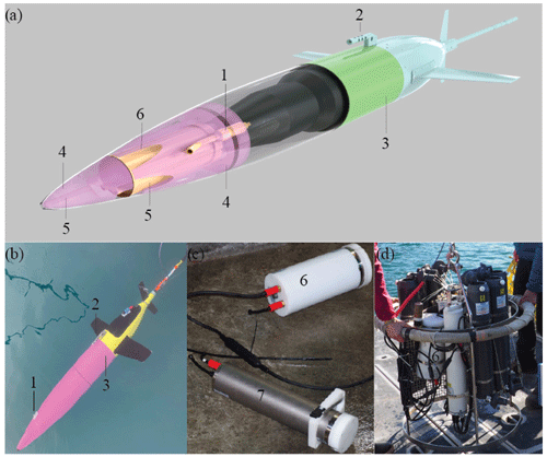
Figure 1CO2 Seaglider. CO2 Seaglider (a) schematic rendering and (b) picture in Resurrection Bay, Seward, Alaska, during a checkout dive on 6 February 2023, before beginning the first winter mission collecting high-resolution pCO2 data. Highlighted are the (1) Sea-Bird 5M pump, (2) conductivity and temperature sail, (3) extension, (4) syntactic foam, (5) water flow channels, and (6) SG HydroC CO2 in a titanium housing, enabling pCO2 observations down to 1000 m. (c) Picture of the new SG HydroC CO2 in a polyoxymethylene housing (6; rated to 300 m depth) and original CONTROS HydroC™ CO2 sensor (7). (d) Picture of the rosette setup for the profiling experiment.
Since the equilibration time (response time) of membrane-based sensors is affected by the exchange of the water mass in front of the sensor head, we installed a Sea-Bird Electronics (SBE) 5M pump next to the SG HydroC CO2 sensor using tubing to transfer seawater from outside the glider fairing to the membrane surface (Fig. 1a). The response time was determined at the manufacturer, verified in the field, and then used to correct for hysteresis during the post-processing phase (see Sect. 2.7.2).
The form factors of the HydroC CO2™ sensor and Seaglider were changed to achieve an internal integration of the sensor with the Seaglider. The standard high-performance HydroC CO2™ sensor was changed from ∅ 89 × 380 to ∅ 136 × 294 mm by rearranging the gas cycle components and the control unit (Fig. 1c). This new SG HydroC CO2 sensor is available in polyoxymethylene cladding rated to 300 m or a titanium housing rated to 1000 m to provide a choice between a coastal mission and an offshore deeper mission. Use of the titanium housing required a syntactic foam housing to compensate for the weight, whereas the polyoxymethylene housing was integrated into the glider with simple brackets (Fig. 2). Despite these adjustments to the size of the sensor, to our knowledge, it is still the largest and heaviest sensor that has been integrated with a Seaglider to date. The forward fairing of the Seaglider was extended by 40 cm with a fiber-glass cylindrical extension to create internal wet-payload space for the sensor, pump, and cables (Fig. 1a and b). The sensor was mounted with the membrane facing aft to ensure that potential bubbles within the internal tubing of the sensor could escape the system during the downcast of the first dive. In situ comparison of the orientation of the sensor and close examination of pCO2 and internal pressure data suggested that the highest data quality was achieved with this mounting design.
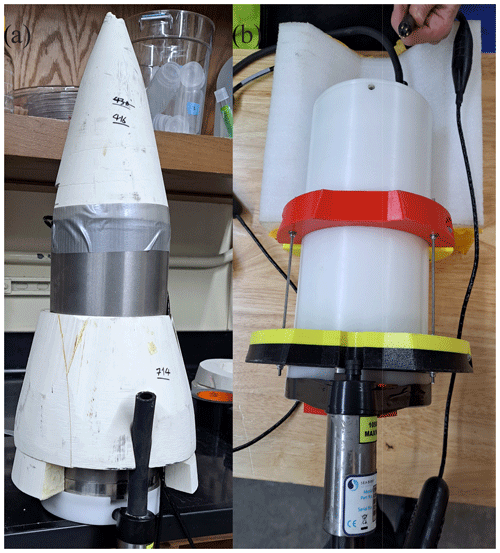
Figure 2SG HydroC CO2 sensor mounting designs. (a) Titanium SG HydroC CO2 (rated to 1000 m) in a custom syntactic foam coat and (b) polyoxymethylene SG HydroC CO2 (rated to 300 m) with brackets.
One of the advantages of using ocean gliders for ocean observing is the ability for real-time communication of data and commands between the pilot and the glider. To take advantage of this, modifications were needed to allow two-way communication between the Seaglider firmware and the HydroC firmware. The Seaglider firmware has a feature to allow easy integration of “logging devices”, which provides a way to build commands for the pilot on land to switch the sensor on and off and change the sampling strategy during the mission (on/off below or above certain depth) when it comes to the surface for a communication session. The Seaglider firmware can also automatically set the clock of the sensor on request at every surfacing and send small samples of the data stream via Iridium along with the standard sensor data. This required the writing and testing of a driver file (CNF file). However, to take full advantage of the ability of the HydroC, a more advanced electronic integration was carried out using Smart Interoperable Real-time Maritime Assembly (SIRMA™, registered trademark of Cyprus Subsea Consulting and Services, C.S.C.S., Ltd.). This small programmable electronic circuit contained hardware elements to adapt the sensor power and communication requirements to those available on the host platform. It also allowed for separate storage and processing capabilities to supplement the main host processor that controls the flight, sampling, and telecommunications of the host. Most importantly here, it was programmed to relay pilot commands to the SG HydroC CO2 for the built-in “zero” function, which isolated the internal gas circuit until there was no CO2 present, measured the concentration signal, and assigned a zero value. Then the gas circuit was exposed to the headspace behind the diffusion membrane for in situ sampling. SIRMA was also programmed to extract raw data from the HydroC and calculate the bin average of some of the output fields, which were useful for real-time mission adaptation and confirmation of sensor operation. Three levels of output were allowed, depending on how much surfacing time could be tolerated before continuing the mission (the baud rate for Iridium is very low: on the order of 4800 bps). More detailed information can be found in the CO2 Seaglider Standard Operating Procedure (SOP) (Irving et al., 2024).
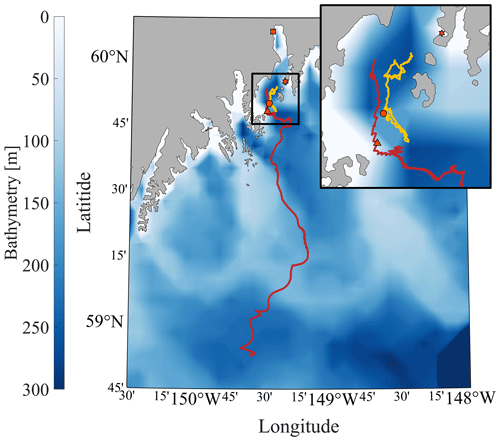
Figure 3Map of the CO2 Seaglider study area. The bathymetry of the Gulf of Alaska is shown in color with a zoomed-in section of the head of Resurrection Bay (outlined black square and inset map). Tracks of the CO2 Seaglider from the 4–7 May 2022 and 8–21 February 2023 missions are shown in yellow and red, respectively. Orange markers outlined in black show the location of the Alutiiq Pride Marine Institute (square), the National Oceanic and Atmospheric Administration's Gulf of Alaska Ocean Acidification mooring (star), the 7 May CTD cast (circle), and the last location where pCO2 data were collected during the February 2023 mission (triangle).
In addition to the HydroC CO2 sensor, the CO2 Seaglider carried an Aanderaa 4831F optode, which is a compact optical oxygen sensor that works on the principle of luminescence quenching by oxygen with a precision of 0.1 µM and an absolute accuracy of ± 2 µM after multipoint calibration. The 4831F was equipped with a fast-response sensing foil with a well-characterized response time of 8 s. The Aanderaa optode measured absolute oxygen concentration and percentage saturation. It is the most widely used on ocean gliders and has been integrated into both Slocum gliders and Seagliders (López-García et al., 2022; Bittig et al., 2018). The OceanGliders community has developed a Standard Operating Procedure (SOP) that details everything from mounting, calibration, available sensors, piloting tips, and response time correction to post-processing (López-García et al., 2022). The CO2 Seaglider was also outfitted with an SBE CT sail and Wetlabs Ecopuck measuring chlorophyll fluorescence at 695 nm.
2.2 CH4 Seaglider
We also integrated a modified version of the CONTROS HydroC CH4 sensor (-4H-JENA engineering GmbH, Kiel, Germany) with the Seaglider. The manufacturer's published uncertainty of the HydroC CH4 sensor is 2 µatm or ± 3 %, whichever is greater. The SG HydroC CH4 sensor had the same form factor as the SG HydroC CO2 sensor. However, it was 0.5 kg heavier due to its tunable diode laser absorption spectroscopy (TDLAS) component, so the SG HydroC CH4 had to be integrated with changes to the glider's ballast.
2.3 Spring and winter CO2 Seaglider missions
Both versions of the CO2 Seaglider (rated to 300 m versus 1000 m) were tested in separate missions (Fig. 3) in spring (53 dives from 4–7 May 2022; Fig. 4) and winter (310 dives from 8–21 February 2023; Fig. 5). The 300 m version with integrated polyoxymethylene housing was tested during the 4–7 May 2022 mission. The glider followed along a transect within Resurrection Bay. Conductivity–temperature–depth (CTD) casts near the glider path allowed for in-depth evaluation of the data quality. The 1000 m depth-rated CO2 Seaglider with integrated titanium housing was tested in February 2023. Estimated energy consumption during the CO2 Seaglider missions was 19 out of 135 Ah and 75 out of 120 Ah for the 24 V which powered the SG HydroC CO2 sensor battery for the spring and winter missions, respectively. Before the February mission, the onboard modem was replaced with a newer model, with different input voltage requirements, which were probably not met as the mission evolved. As a result, the glider could not communicate and was lost. While this was an unfortunate mistake, the loss of the glider had nothing to do with the HydroC CO2 integration.
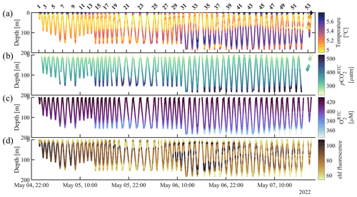
Figure 4CO2 Seaglider data from the 4–7 May 2022 mission in Resurrection Bay, Seward, Alaska. Depth profiles of (a) temperature (°C), (b) response-time-corrected pCO2 (pCO, µatm), (c) response-time-corrected O2 (O, µM), and (d) raw chlorophyll fluorescence. The diamonds show discrete values that were taken during a CTD cast (Table 3).
2.4 Tank experiments
Shortly before the May 2022 glider mission, the glider was kept in a flow-through tank at the Alutiiq Pride Marine Institute for roughly 12 h for cross-calibration purposes. The flow-through tank was fed with water from about 75 m depth and 91 m from the laboratory into Resurrection Bay, near a freshwater source. During the tank experiment, SG HydroC CO2T-0718-001 (Fig. 6b, blue line) was integrated into the Seaglider, and the SG HydroC CO2T-0422-001 (Fig. 6b, black line) and SG HydroC CH4 (Fig. 6c) sensors were secured next to the Seaglider. The water was kept in motion with a circulation pump. Triplicate discrete water samples for dissolved inorganic carbon, pH, and pCH4 analysis were taken every 4 h (Table 1).
Table 1Tank experiment. Evaluation of SG HydroC CO2 and SG HydroC CH4 sensors compared to reference discrete pCO and pCH. Units of pCO2 and pCH4 are micro-atmospheres (µatm) except when shown as a percent difference in parentheses (Eq. 1). Columns with subscripts sn422 and sn0718 indicate data from sensors HydroC CO2T-0422-001 and HydroC CO2T-0718-001, respectively. The superscript RTC indicates response-time-corrected values following Dølven et al. (2022). pCO and pCH values are the average of triplicate bottles and are shown in Fig. 6.

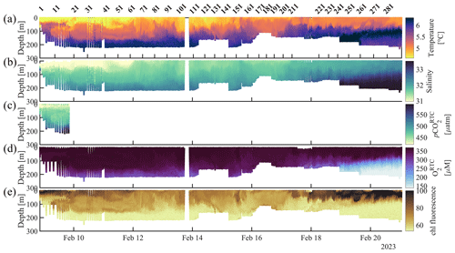
Figure 5CO2 Seaglider data collected during the 8–21 February 2023 winter mission. Shown are (a) temperature (°C), (b) salinity, (c) response-time-corrected pCO2 (pCO, µatm), (d) response-time-corrected oxygen (O, µM), and (e) raw chlorophyll fluorescence (chl fluorescence) as time and dive number vs. pressure.
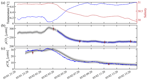
Figure 6Sensor validation during a tank experiment at the Alutiiq Pride Marine Institute on 1–2 May 2022. (a) Temperature (blue line) and salinity (red line) from a recently calibrated Sea-Bird Scientific SBE37. (b) Black (blue) lines show pCO2 in micro-atmospheres (µatm) from HydroC CO2T-0422-001 (HydroC CO2T-0718-001), with the shaded gray (blue) areas showing a relative uncertainty of 2.5 % (weather quality goal; Newton et al., 2015). Black circles with red filling show discrete pCO, with error bars showing the combined standard uncertainty from errors.m (Orr et al., 2018). HydroC pCO2 data are shown at 1 min resolution with a 2 min moving median filter applied and have not been corrected for response time, but differences were negligible (< 0.1 µatm). (c) The black line shows pCH4 in micro-atmospheres (µatm) from HydroC CH4T-0422-001, with the shaded gray bar showing an uncertainty of 2 µatm. The blue line is the response-time-corrected signal with a response time of 43 min following Dølven et al. (2022). HydroC pCH4 data are shown at 1 min resolution with a 2 min moving median filter applied to the raw data and a 10 min moving median filter applied to the RTC data. Black diamonds with red filling show discrete pCH, and all discrete values of pCO and pCH are the average of triplicate bottles.
2.5 Rosette package
One of the SG HydroC CO2 sensors (CO2T-0422-001) was installed on an SBE-55 frame ECO water sampler with six 4 L sample bottles (Sea-Bird Scientific) during the May 2022 trials (Tables 2 and 3; Figs. 7 and S1). The SBE-55 and SG HydroC CO2 were powered by an SBE-33 carousel deck unit. The SG HydroC CO2 interfered with the communication stream and thereby prevented real-time data acquisition and control of the SBE-55, but data were internally logged. The depth of the rosette package was monitored directly on the winch, and the timing of firing of the sample bottles, after an approximate 15 min hovering period (to allow for equilibration), was programmed in advance based on time intervals. On 3 May (Table 2; Fig. 7) only samples from the upper 20 m of the water column were usable due to issues with manually measuring the depths and the sample collection. On 7 May (Table 3; Fig. S1) two bottles that were intended to be fired while the rosette was stationary at depth, were instead fired while the rosette was in motion.
Table 2Profiling experiment. Evaluation of the SG HydroC CO2 sensor compared to reference discrete pCO. Units of pCO2 are micro-atmospheres (µatm) except when shown as a percent difference in parentheses (Eq. 1). pCO2 with the subscript “Rosette” indicates data from the HydroC sensor mounted on the rosette (HydroC CO2T-0422-001). The superscript RTC indicates response-time-corrected values following Dølven et al. (2022).
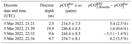
Table 3Seaglider HydroC evaluation with a nearby cast. Evaluation of Seaglider-integrated and rosette-mounted SG HydroC CO2 sensors compared to pCO collected from a nearby cast. Units of pCO2 are micro-atmospheres (µatm) except when shown as a percent difference in parentheses (Eq. 1); differences of pCO were calculated using the average (upcast and downcast combined) 1 m binned data. The superscript RTC indicates response-time-corrected values following Dølven et al. (2022), and the subscripts “Rosette” and “Seaglider” indicate the SG HydroC CO2 sensor mounted on the rosette (SG HydroC CO2T-0422-001) and integrated into the Seaglider (SG HydroC CO2T-0718-001), respectively. The time delay (HH:MM) and spatial distance (km) columns represent the distance of pCO measured at the discrete depth and the discrete date and time. The asterisk (*) indicates the comparison with pCO taken as nearest in time before sensor zeroing (Fig. S1).

2.6 Discrete water samples
2.6.1 Inorganic carbon chemistry
Discrete seawater samples were collected for sensor validation in two different cases in May of 2022. Firstly, samples were taken alongside two SG HydroC CO2 sensors during a tank experiment at the Alutiiq Pride Marine Institute (Fig. 6b; Table 1) (Fig. 1d). Secondly, samples were taken from bottles during a CTD cast within 1 km and 4 h of the HydroC measuring pCO2 on the glider while conducting dives (Sect. 3.2).
Inorganic carbon sampling in the Gulf of Alaska's glaciated coastal regions requires methodological variations from open-ocean best practices to ensure that suspended mineral particles do not compromise the instrumentation and/or bias measurements between sample collection and analysis (Sejr et al., 2011). Given this, the discrete seawater samples were filtered (replaceable 0.45 µm filter in a 47 mm polycarbonate in-line filter) with a peristaltic pump straight from the Niskin bottles (see Bockmon and Dickson, 2014, for detailed methods) or tank into pre-cleaned 500 mL borosilicate bottles and poisoned with 200 µL mercuric chloride (HgCl2) (Dickson et al., 2007). Samples were transported and stored at room temperature before analysis. Samples were opened immediately (< 10 min) before concurrent analyses of pH and dissolved inorganic carbon (DIC) to limit gas exchange with ambient lab conditions. Samples were analyzed for DIC using an Apollo SciTech, LLC dissolved inorganic carbon analyzer model AS-C6. All species of dissolved inorganic carbon in a sample were converted to CO2 by the addition of a strong acid. The CO2 gas was then purged from the sample through a drying system. The concentration of CO2 gas was measured using a nondispersive infrared gas analyzer, the LI-7000 CO2 H2O analyzer. This method required Certified Reference Material (CRM; batch 198 from Andrew Dickson's Certified Reference Materials Laboratory) to create a three-point calibration line. The calibration line was used to quantify the total amount of CO2 in the sample as the integrated area under the concentration–time curve. Apollo SciTech recommendations to improve analytical accuracy were followed and included bubbling of CO2 off the acid daily; allowing the analyzer to warm up for at least 2 h before measurements begin; measuring a set of standards at the beginning and end of each day and every nine samples; using ultrahigh-purity (UHP) N2 gas; and filtering the N2 gas with a PTFE filter, CO2 scrubber (Ascarite II), and H2O scrubber (Mg(ClO4)2).
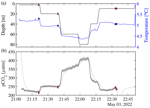
Figure 7Profiling experiments from 3 May 2022 with the HydroC CO2T-0422-001 sensor mounted on the rosette. (a) Pressure vs. time on the left (black) axis, with diamonds showing rosette CTD values of pressure (filled red diamond), and temperature vs. time on the right (blue) axis as well as temperature (filled blue diamond) at the time of the bottle fire. (b) pCO2 measured by the rosette-mounted SG HydroC CO2 sensor as a raw (gray line) and response-time-corrected signal (thick black line; pCO in Table 2), with shaded relative uncertainty of 2.5 % (weather goal; Newton et al., 2015). pCO shown as red diamonds, with vertical red error bars showing combined standard uncertainty (Orr et al., 2018). Table 2 shows differences between discrete pCO and pCO. The SG HydroC CO2 sensor started a zeroing interval at 22:35 on 3 May 2022, so pCO is not shown after that time but signal recovery can be seen in the uncorrected signal (gray line).
Samples were analyzed spectrophotometrically for pH with a CONTROS HydroFIA pH (Aßmann et al., 2011) operating in discrete measurement mode using unpurified metacresol purple (mCP) as the indicator dye (Clayton and Byrne, 1993). Sample temperature was stabilized at 25.00 ± 0.01 °C during measurements using Peltier elements, and five repetitive measurements were taken for each sample. At the beginning of each day, the HydroFIA pH underwent a conditioning period using seawater with similar properties until values stabilized. CRMs (known TA and DIC concentration; batch 198 from Andrew Dickson's Certified Reference Materials Laboratory) were measured at the beginning and end of the day, as well as every nine samples.
All data processing and analyses were done using an in-house MATLAB routine. In situ pH and pCO were calculated from input pair pHlab and DIC using CO2SYSv3 (Sharp et al., 2023) with dissociation constants for carbonic acid of Sulpis et al. (2020), bisulfate of Dickson (1990), hydrofluoric acid of Perez and Fraga (1987), and the boron-to-chlorinity ratio of Lee et al. (2010). pHlab is defined as the pH measured on the total scale at measurement temperature and 1 atm of pressure (0 dbar applied pressure) using spectrophotometic methods, with instrument specifications described above. Sulpis et al. (2020) found that the carbonic acid dissociation constants of Lueker et al. (2000) may underestimate pCO2 in cold regions (below ∼ 8 °C) and therefore overestimate pH and carbonate ion concentrations (CO). Differences between discrete pCO2 calculated with the carbonic acid dissociation constants by Lueker et al. (2000) (the standard in synthesis data products; e.g., Jiang et al., 2021; Lauvset et al., 2022; Metzl et al., 2024) and the HydroC pCO2 from the tank experiment were found to be on average 4.6 µatm (1.6 %) and 4.2 µatm (0.7 %) greater for SN0422 and SN0718, respectively, when compared with discrete pCO2 based on carbonic acid dissociation constants by Sulpis et al. (2020).
Discrete pCO2 uncertainty (uc) was calculated as the combined standard uncertainty from errors.m (Orr et al., 2018) that propagates input uncertainties plus errors in the dissociation constants. Input uncertainties for pHlab and DIC were the standard uncertainties, defined as the square root of the sum of the squared random uncertainty component plus the squared systematic uncertainty components. For pHlab the random uncertainty was the sample precision, or standard deviation of the measurements. For DIC, the random uncertainty was the propagated error calculated with the first-order Taylor series expansion (Eq. 1; Orr et al., 2018) and assuming the correlation term was zero for the conversion of molarity (µmoles L−1) to molality (µmoles kg−1). Systematic uncertainty components were the uncertainty in the CRM used for instrument offset and drift correction, as well as the published instrument accuracy, or, if available, the daily instrument accuracy as defined below. Daily instrument accuracy was defined as the maximum difference between the known CRM concentration and the measured CRM concentration after data were corrected for instrument drift and offset of all available CRMs not used in the instrument drift and offset calculation. CRM pHlab “known” values were calculated using CO2SYSv3 (Sharp et al., 2023) with inputs TA and DIC. Nutrient concentrations (SiO, PO) were assumed to be negligible in the CO2SYS calculations (e.g., DeGrandpre et al., 2019; Vergara-Jara et al., 2019; Islam et al., 2017).
2.6.2 Methane
Two sets of triplicate pCH4 discrete water samples were collected during the tank experiment for an initial evaluation of the SG HydroC CH4 sensor (Table 1, Fig. 6c). Seawater was filtered from the tank into 250 mL vials. The vials were closed with a rubber stopper, topped with an aluminum cap, and closed with a crimp immediately. A dry and clean syringe was flushed with 10 mL of N2 gas twice. The third fill was kept, and the syringe valve was closed. N2 was then injected into the headspace while simultaneously pulling 10 mL of seawater out of the vial using a second syringe. 50 µL mercuric chloride (HgCl2) was added to the vial, which was then shaken for about a minute and put into a fridge at 4 °C for over 12 h to equilibrate the headspace. The samples were then sent to the Kessler analytical laboratory at the University of Rochester for methane concentration analysis following previously published procedures (Leonte et al., 2020).
2.7 Data post-processing
2.7.1 pCO2 post-processing
SG HydroC CO2 data were post-processed using Jupyter Notebook scripts developed by -4H-JENA engineering GmbH at the original resolution (2 s). SG HydroC CO2 (SG HydroC CO2T-0422-001) data from the tank experiment (Table 1; Fig. 6) and rosette-mounted CTD casts (Tables 2 and 3; Figs. 7 and S1) were post-processed to correct for baseline drift (change in the zero signal reference) and span drift (changes in the sensor's concentration dependent characteristics) using pre- and post-calibration coefficients interpolated over the deployment (Fietzek et al., 2014). For the May 2022 Seaglider-integrated SG HydroC CO2 sensor (SG HydroC CO2T-0718-001; Table 3; Figs. 4 and 8), data were post-processed with pre-calibration coefficients only (no span drift correction) because the sensor was damaged during the return shipment for post-calibration. Differences between sensors remained low despite the difference in processing, with a mean difference during the tank experiment of 2.1 ± 1.0 µatm (0.9 %) and median difference of 2.0 ± 1.0 µatm (0.9 %) (Table 1; Fig. 6b). The pCO2 data from February 2023 were collected with a sensor that was factory-calibrated 2 weeks prior to deployment (SG HydroC CO2T-0422-001) but were not post-processed because a required parameter (p_NDIR) was not relayed in real time and the glider was lost. Lack of post-calibration most likely had no negative effect on the quality of data since the HydroC only collected data for ∼ 4 d during the spring mission and ∼ 2 d during the winter mission.
HydroC pCO2 and pCO data at the original resolution (2 s) and RTC resolution (8 s) were linearly interpolated onto the Seaglider timestamp, and 1 m binned data were calculated by first averaging 1 m (± 0.5 m) upcast and downcast data independently, linearly interpolating over gaps, and then averaging the interpolated 1 m binned upcasts and downcasts together.
2.7.2 Response time correction
The ability to determine the in situ response time (τ63 of the HydroC, which took into account membrane characteristics and the rate of water exchange over the membrane, i.e., pump characteristics) of the sensor made correction for hysteresis through data post-processing possible. This is critical for a sensor operating on profiling platforms, especially in the Gulf of Alaska, where strong environmental gradients were encountered. Fiedler et al. (2013) used a CONTROS HydroC™ CO2 with a silicone polydimethylsiloxane (PDMS) membrane and reported a linear response time dependency on water temperature on the order of 1 s per 1°C. For this study, the SG HydroC CO2 sensors were deployed with the new robust TOUGH membrane, which had Teflon AF2400 as the active separation layer with a low temperature dependence on the permeability coefficient (Pinnau and Toy, 1996). Response times determined during calibration at -4H-JENA were used for response time correction (RTC) and found to be 106 s for the HydroC mounted on the rosette in May 2022 and 108 s when it was integrated into the Seaglider in February 2023 (HydroC CO2T-0422-001). The response time of the HydroC integrated into the Seaglider in May 2022 (HydroC CO2T-0718-001) was 109 s. Since field verification of the response time was recommended to ensure the highest-quality post-processed data product (because τ63 can be affected by the speed of water exchange across the membrane due to pump speed, tube length, etc.), we verified the sensor response time at deployment. After the glider was stationary for approximately 15 min, a zeroing interval was performed with the HydroC CO2 sensor. The response time was determined by reviewing the time it took for the signal to recover to the ambient concentration. Our in situ response time tests were suggested to be within 5 s of the response time found during calibration (not shown). Before RTC was applied, HydroC CO2 data were smoothed using a quadratic regression (MATLAB's smoothdata.m function with the loess method) over a 2 min window. This was done to eliminate erroneous spikes in the RTC signal while retaining the original 2 s resolution of the pCO2 data. The RTC resolution of 8 s was determined with the L-curve analysis included in the publicly available code from Dølven et al. (2022). The Dølven et al. (2022) RTC method was used because it produced more realistic profiles than an RTC method (Miloshevich et al., 2004; not shown) previously used for HydroC CO2 correction from a profiling float (Fielder et al., 2013). In addition, Dølven et al. (2022) developed their algorithm with equilibrium-based sensors in mind, and it was proven with a sensor with a long response time (HydroC CH4 τ63≅23 min).
2.7.3 pCH4 post-processing
SG HydroC CH4 data were response-time-corrected using a τ63 of 43 min (Dølven et al., 2022; Fig. 6c, blue line). Before RTC was applied, HydroC pCH4 data were smoothed using a quadratic regression (MATLAB's smoothdata.m function with the Loess method) over a 2 min window to avoid erroneous spikes in the RTC data while retaining the original 2 s resolution of the pCH4 data. The RTC resolution of 30 s was determined with the L-curve analysis included in the publicly available code from Dølven et al. (2022). Discrete pCH4 samples were collected during the tank experiment (Table 1; Fig. 6c, red diamonds) and analyzed at the Kessler analytical laboratory at the University of Rochester for methane concentration analysis following previously published procedures (Leonte et al., 2020). Discrete pCH4 sample values were converted from the concentration of dissolved gas in water (mol L−1) to partial pressure (pCH, µatm) using the solubility coefficient following Sarmiento and Gruber (2006). pCH uncertainty (u; Table 1; Fig. 6c, red error bars) was calculated as the square root of the sum of the squared (1) mean of the standard deviations from each sample as returned from the lab and (2) the standard deviation of the triplicates.
3.1 Glider flight
The CO2 Seaglider was able to “fly” properly, allowing the desired undisturbed flow, despite the large payload and major changes to the vehicle fairing. Example flight profiles with the polyoxymethylene and titanium integrated sensors are shown in Figs. 9 and 10, respectively. Pitch and vertical velocity are in the stable range and roughly symmetric between downcast and upcast, indicating a nearly balanced glider. Heading varies around the targeted value as the roll adjusted to heading errors. It should be noted that this level of variability is typical of standard Seagliders. Operating Seagliders in shallow water (< 200 m) is risky because of the likelihood of meeting depth-averaged currents of the same order of magnitude as the vehicle speed. A typical single dive cycle of downcast and upcast shows that the sensor data are free of noise that could be expected if there were recirculated water from the glider meeting the sensors. The expected endurance of the CO2 Seaglider is around 18 and 15 d for the CH4 Seaglider with constant sampling at full depth.
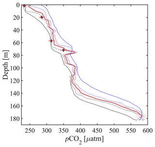
Figure 8CO2 Seaglider data from a single dive during the 4–7 May 2022 mission in Resurrection Bay, Seward, Alaska. Depth profile of pCO2 in micro-atmospheres (µatm) showing the original-resolution smoothed pCO2 (downcast: solid black, upcast: solid blue), RTC pCO2 following Dølven et al. (2022) (dashed black line: downcast, dashed blue line: upcast), and 1 m binned RTC profile (thick red line) with red shading showing the relative uncertainty of 2.5 %. Discrete pCO2 (pCO) is shown as red diamonds, with horizontal red error bars showing combined standard uncertainty (Orr et al., 2018). Differences between pCO and pCO are shown in Table 3.
3.2 CO2 Seaglider data evaluation
The quality of the CO2 Seaglider data was thoroughly tested with discrete measurements during a tank experiment, nearby CTD cast, and glider missions.
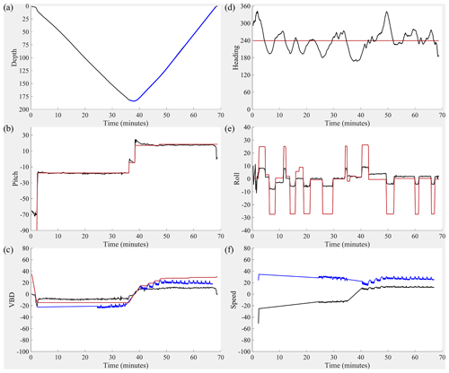
Figure 9Dive details for the 300 m rated CO2 Seaglider (dive 51). (a) Depth (black line; meters), (b) pitch (black line; degrees) with pitch control (red line; mm of battery shift), (c) change in displacement of variable buoyancy drive (VBD) (red line; units of 10 cc), vertical velocity from pressure measurements (black line; cm s−1), buoyancy (blue line; units of 10 g), (d) heading (desired: red line, measured: black line; degrees), (e) roll (battery roll position: red line, glider-measured roll: black line; degrees), and (f) vertical speed (calculated from buoyancy and pitch; black line; cm s−1) and horizontal speed (calculated from buoyancy and pitch; blue line; cm s−1).
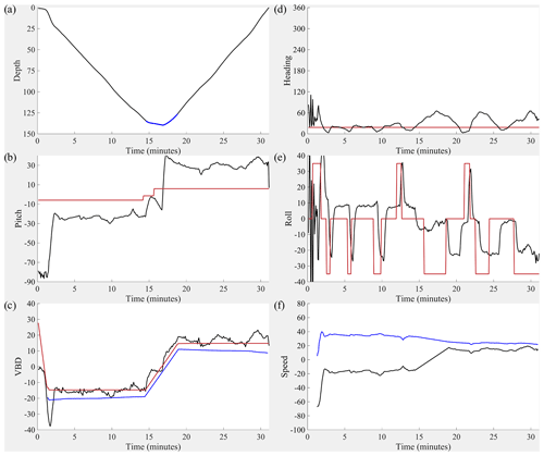
Figure 10Dive details for the 1000 m rated CO2 Seaglider (dive 203). (a) Depth (black line; meters), (b) pitch (black line; degrees) with pitch control (red line; mm of battery shift), (c) change in displacement of variable buoyancy drive (VBD) (red line; units of 10 cc), vertical velocity from pressure measurements (black line; cm s−1), buoyancy (blue line; units of 10 g), (d) heading (desired heading: red line, measured heading: black line; degrees) (e) roll (battery roll position: red line, glider-measured roll: black line; degrees), and (f) vertical speed (calculated from buoyancy and pitch; black line; cm s−1) and horizontal speed in centimeters per second (calculated from buoyancy and pitch; blue line; cm s−1).
3.2.1 Tank experiment
Discrete water samples show good agreement with the SG HydroC CO2 sensors (Fig. 6b; Table 1). The values of discrete water samples represent the average of triplicate samples (Fig. 6c, red diamonds). Differences between the SG HydroC CO2 sensors remained low, with a mean difference during the tank experiment of 2.1 ± 1.0 µatm (0.9 %) and median difference of 2.0 µatm (0.9 %; Table 1). Percent differences (Eq. 1) between the SG HydroC CO2 sensors and discrete water samples collected in the tank were between −1.4 % and 1.9 % (Table 1; Fig. 6).
3.2.2 Profiling experiment
Rosette-based profiles with the SG HydroC CO2 sensor in combination with discrete water samples were used to test and evaluate the response time correction algorithm by Dølven et al. (2022). The rosette was lowered into the water and kept at different depths for about 20 min at a time (Figs. 7a and S1a). Sample bottles were programmed to collect seawater toward the end of each hovering period. pCO2 measured with the HydroC ranged from 218 µatm at the surface to 411 µatm at 80 m depth on 3 May (Fig. 7b) and 231 µatm at the surface to 382 µatm at 77 m depth on 7 May (Fig. S1). Differences between the rosette-mounted SG HydroC CO2 sensor and discrete samples ranged from −3.3 µatm (−1.4 %) to 8.2 µatm (3.5 %), with the lowest percent difference of 0.6 % (Table 2) on 3 May, and from −5.7 µatm (−1.6 %) to 12.1 µatm (3.9 %), with the lowest percent difference of 0.3 % (Table 3) on 7 May.
3.2.3 Data evaluation during CO2 Seaglider mission
The quality of the pCO2 data from the CO2 Seaglider was further evaluated during a 4–7 May sea trial mission in spring 2022 in Resurrection Bay, Alaska (Fig. 3).
Discrete water samples were taken in proximity (1 km and within 4 h) to the downcast of dive 51 (Table 3; Figs. 4a and 8). The response-time-corrected CO2 Seaglider data compare well with the discrete water samples (Fig. 8), overestimating the discrete water samples between 8.3 µatm (2.7 %) and 12.0 µatm (5.1 %) (Table 3). The mean difference between the rosette-mounted and Seaglider-integrated SG HydroC CO2 sensors during the 7 May cast at the time of discrete samples was 8.5 µatm ± 8.9 µatm (3.7 %). The larger difference between SG HydroC CO2 sensors compared to the difference during the tank experiment (see Sect. 3.2.1) is unsurprising, given the spatial and temporal distance between sensors (Table 3). Collecting more discrete samples throughout the water column and in closer proximity (within 100 m; Thompson et al., 2021) to the CO2 Seaglider conducting dives would allow a more tightly constrained uncertainty estimate for response-time-corrected pCO2 data collected on a glider and should be a priority for future researchers.
3.3 CH4 Seaglider data evaluation
Tank experiment
The SG HydroC CH4 sensor was also evaluated during the tank experiment described in Sect. 2.4 (Fig. 6c). Percent differences (Eq. 1) between discrete pCH4 (average of triplicate samples) and pCH were 6.6 % to 15.8 % (Table 1). During the experiment, there was a decrease in salinity from 30.95 to 29.88, where pCO2 decreased by 80 µatm. The corresponding pCH signal decreased by 25.4 µatm from 32.3 to 6.9 µatm. Although the triplicate discrete pCH4 water samples were slightly lower than the sensor-measured pCH4 values, they also reflected this step change.
3.4 Winter and springtime pCO2 in Resurrection Bay, Alaska
The surface-to-subsurface pCO2 gradient is much larger in spring than in winter (Fig. 11). During the 4–7 May mission, the average surface pCO was 240.7 ± 16.5 µatm (mean ± standard deviation at 2 m) with an average temperature of 5.8 ± 0.4 °C (Figs. 4 and 11). In February, surface pCO was near atmospheric pCO2 (427.4 ± 13.0 µatm, temperature 4.1 ± 0.3 °C) and about 180 µatm higher than in May (Figs. 5 and 11). NOAA's moored sensor located in Sunny Cove (59.911° N, −149.35° W), near the CO2 Seaglider trial site, measured an average sea surface pCO2 of 240.7 ± 10.4 µatm during the time of the May 2022 mission (Monacci et al., 2023), which compared remarkably well with the Seaglider-based measurements. A minimum of 140 µatm was measured in Sunny Cove in mid-April (3 d average) (Fig. 12; Monacci et al., 2023), suggesting that the peak of the spring bloom happened 3 weeks before the May 2022 glider mission. Since we do not have salinity data from the May CO2 Seaglider mission (conductivity sensor failure), we cannot disentangle the contributions of freshwater or primary production to the low surface pCO2 values observed (Fig. 4). The moored sensor in Sunny Cove measured an average sea surface pCO2 of 416.4 ± 4.2 µatm during the time of the February mission, straddling the atmospheric pCO2 values (Monacci et al., 2023; Fig. 12). Subsurface pCO at 180 m was on average 545.6 ± 16.9 µatm during the February mission and 518.2 ± 37.4 µatm during the May 2022 mission (Fig. 11a). pCO2 was much lower in May than in February throughout the upper water column (< 120 m), whereas there was not much of a seasonal difference at deeper depth. Some of the fine-scale features apparent in the May pCO2 and O2 profiles are likely due to various levels of photosynthetic activity (Fig. 11). As the glider transitioned into the open Gulf of Alaska during the February mission, water with O2 < 150 µM shoaled into the upper 150 m of the water column (Fig. 5). Unfortunately, the HydroC CO2 sensor was turned off at that stage of the mission to conserve battery.
The newly developed CO2 Seaglider is the first of its kind to autonomously collect high-quality pCO2 data. The tank and rosette experiments and in situ data evaluation suggest that the post-processed data from the CO2 Seaglider generally fall near the relative uncertainty of 2.5 %, which is a threshold defined as the “quality sufficient to identify relative spatial patterns and short-term variation” (“weather quality”; Newton et al., 2015). This is the highest quality of pCO2 data measured with a subsurface autonomous vehicle to date and therefore an important step towards filling the subsurface carbonate system data gap. -4H-JENA is reassessing their sensor calibration methodology and data post-processing algorithm to further improve the HydroC's data accuracy.
The newly developed CO2 Seaglider is suitable for data collection in open-ocean or coastal environments with bottom depths deeper than 300 m. However, the coastal Gulf of Alaska is a highly dynamic environment, with strong freshwater and wind influence, as well as rugged shallow (often < 200 m) bottom topography. Strong currents (up to 0.50 m s−1) made the piloting of the glider extremely difficult throughout the project and confirmed that the Seaglider cannot reliably reach desired waypoints in these conditions. The current version of the CO2 Seaglider is also not suitable for operating in the coastal Gulf of Alaska in summer and early fall due to strong seasonal salinity gradients in this freshwater-influenced area. Another issue we faced was the fact that the forward-looking altimeter could not detect the seafloor as it should in its position behind the HydroC CO2 sensor. In areas with detailed topography maps this would not be an issue, but in the coastal Gulf of Alaska reliable topography information is not readily available yet. An obvious next step is to integrate the SG HydroC CO2 sensor into a newer glider platform, such as the Seaglider SGX or Teledyne Slocum G3 glider. The extended energy bay, larger buoyancy range, and thruster should make the operation of the coastal Slocum G3 with HydroC sensors relatively easy and would allow for autonomous high-resolution water column measurements of pCO2 and pCH4 in dynamic coastal environments. The integration of a HydroC on a Slocum glider will require a custom-made wet-payload bay due to the size of this sensor. For open-ocean or deeper coastal regions, the integration with the Seaglider SGX, with 60 % higher energy capacity, would be effective and nearly identical to the work already done here.
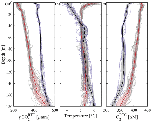
Figure 11Averaged CO2 Seaglider profiles from the 4–7 May 2022 and 8–21 February 2023 missions in Resurrection Bay, Seward, Alaska. Depth profiles of all 1 m binned dives (dotted gray) and the average 1 m binned dive from the May 2022 mission (thick red line; dives 1–51 at 00:01 UTC on 5 May to 16:37 UTC on 7 May 2022) and February 2023 mission (thick black line; dives 1–17 at 20:50 UTC on 8 February to 19:54 UTC on 9 February 2023), with shading showing the standard deviation of the values in each bin added and subtracted from the average. (a) Response-time-corrected pCO2 (pCO, µatm), (b) temperature (°C), and (c) response-time-corrected oxygen (O, µM).
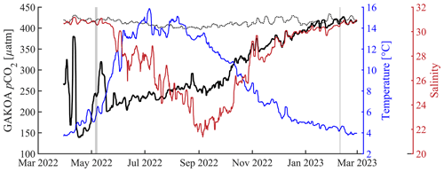
Figure 12The National Oceanic Atmospheric Administration's Gulf of Alaska ocean acidification surface time series from March 2022–2023. Left axis: sea surface (dotted black line) and air (black line, 4 m above sea level) pCO2 (µatm); right axis: sea surface temperature (blue, °C) and sea surface salinity (red). All data are shown as a 3 d running mean. Vertical shaded gray areas highlight the CO2 Seaglider missions in May 2022 and February 2023. The mooring is located at 59.911° N, −149.35° W (Monacci et al., 2023).
The SG HydroC CH4 sensor was successfully integrated into the Seaglider as part of this project. While tank experiments showed promising results, short field tests of the CH4 Seaglider in shallow water revealed low and patchy methane concentrations near the detection limit (not shown). The CH4 Seaglider requires further testing in environments with strong pCH4 gradients during longer and deeper dives (to allow for equilibration) to assess the accuracy of its response-time-corrected data in the field. The sensor's slow response time likely limits the glider to providing qualitative rather than quantitative results. However, due to the scarcity of oceanic CH4 observations, deploying a CH4 glider can help identify the location of methane sources and guide the placement of in situ observations to conduct a more quantitative assessment of CH4 fluxes and dynamics.
Ocean gliders are part of the Intergovernmental Oceanographic Commission (IOC-UNESCO) Global Ocean Observing System (GOOS) through the OceanGliders program (https://www.oceangliders.org/, last access: 14 October 2024). Like other elements of the GOOS coordinated by OceanOPs of the Observation Coordination Group (floats, buoys, moorings, ships, and tide gauges), OceanGliders contributes to ocean observation for climate, ocean health, and real-time services. CO2 gliders are perfectly suited to contribute data for understanding relevant inorganic carbon processes in coastal shelf and boundary regions where mesoscale or sub-mesoscale variability dominates. The current work can also serve as a first step to bring together interested scientists and engineers to further develop and improve the capability of gliders to measure high-quality data. OceanGliders supports this effort by promoting the formation of volunteer international task teams, for which a task team could be requested for oceanographic greenhouse gas research. By doing this, the visibility and availability of data will be improved as well, since GOOS provides an interactive data platform for all its programs (https://www.ocean-ops.org/board, last access: 14 October 2024). An OceanGliders task team could also be linked with the GOOS-sponsored Global Climate Observing System (GCOS: https://gcos.wmo.int/en/home, last access: 14 October 2024) program through their Ocean Observations Physics and Climate Panel (OOPC): a scientific expert advisory group charged with making recommendations for a sustained global ocean observing system for climate.
Near-real-time and high-resolution water column data that can be retrieved from gliders outfitted with sensors measuring salinity, temperature, inorganic carbon system parameters, oxygen, and pCH4 are key to tackling a variety of today's climate-change-related issues. These datasets will become instrumental in advancing biogeochemical model forecasting and early warning systems for extreme heat, acidity, and oxygen compound events that affect coastal subsistence communities, commercial fisheries, and mariculture. Furthermore, using biogeochemical gliders to monitor the environment of tagged organisms (e.g., crabs, fish) would provide insight into the organisms' position and behavior relative to important environmental drivers across susceptible ecosystems. Such biogeochemical glider data will help build a bridge between in situ chemical and biological measurements and environmental change with impacts on biology, thereby filling an important research gap (Widdicomb et al., 2023). Potentially large natural and anthropogenic sources of CH4 may become contributors to climate change and, if oxidized, to ocean acidification (Garcia-Tigreros et al., 2021; Sparrow et al., 2018; Shakhova et al., 2010; Rees et al., 2022). These CH4 sources need to be properly assessed and quantified, and if characterized as having anthropogenic origins, emitters must be held accountable (Goodman et al., 2022). Once the combined HydroC CH4–CO2 sensor is available it will provide a new tool to co-measure pCH4 and pCO2 and give valuable insight into these processes and feedback mechanisms. Other advancing fields, such as marine carbon dioxide removal (mCDR) and the monitoring, verification, and reporting (MRV) thereof, will also need detailed knowledge of the distribution of CO2 in the water column (National Academies of Sciences, Engineering, and Medicine, 2022).
The CO2 Seaglider has been extensively tested and is ready to be used in open-ocean environments. An important next step will be to integrate the HydroC CO2 and CH4 sensors into a glider platform that reliably functions in shallow and freshwater-affected coastal areas, such as the Gulf of Alaska, to be able to fill the large spatial and temporal data gap in these highly dynamic areas.
The CO2 Seaglider data are publicly available at https://doi.org/10.17882/100964 (Hauri et al., 2022) and https://doi.org/10.17882/100965 (Hauri et al., 2023). The HydroC-specific SIRMA code and CNF file are available on GitHub at https://github.com/Cyprus-Subsea/Smart-Cable-HydroC (Cyprus Subsea, 2024a) and https://github.com/Cyprus-Subsea/Smart-Cable-HydroC/tree/main/docs (Cyprus Subsea, 2024b). More detailed information on the HydroC–glider integration and operation can be found in the CO2 Seaglider Standard Operating Procedures at https://britairving.github.io/Carbon_Dioxide_SOP/README.html (Irving et al., 2024).
The supplement related to this article is available online at: https://doi.org/10.5194/os-20-1403-2024-supplement.
CH and AMPM developed the research ideas and the proposal that funded this work. CH led the fieldwork and writing of this manuscript. BI led the preparation for fieldwork and glider data processing and analysis. DH led glider piloting for all trials. DH and EA assisted with data processing, sensor programming, mechanical integration, glider ballasting, deployment, and recovery. NK and JK provided technical support for the HydroC sensors. All authors contributed to the writing of this manuscript.
Authors Dan Hayes and Ehsan Abdi are employed by AOOI and CSCS (respectively) and their objective is to support the ocean research community by providing innovative, cutting-edge observing technological solutions. These include autonomous platforms and related services in unique configurations. Through the support of the National Science Foundation and the National Oceanographic Partnership Program, AOOI was able to jointly develop the CO2 and CH4 gliders and prove and improve the scientific utility of this approach. Authors Nadja Kinski and Jöran Kemme are employed by -4H-JENA engineering GmbH, the manufacturer of the HydroC CO2 and CH4 sensors. The objective of -4H-JENA engineering GmbH is to provide the best possible accuracy of dissolved gas measurements on any platform and under any environmental conditions. Intensive collaboration with scientists is essential for the development of these products.
Publisher's note: Copernicus Publications remains neutral with regard to jurisdictional claims made in the text, published maps, institutional affiliations, or any other geographical representation in this paper. While Copernicus Publications makes every effort to include appropriate place names, the final responsibility lies with the authors.
The Seaglider field trials took place on the traditional and contemporary hunting grounds of the Sugpiaq People. We also acknowledge that our Fairbanks-based offices are located on the Native lands of the Lower Tanana Dena. The Indigenous Peoples never surrendered lands or resources to Russia or the United States. We acknowledge this not only because we are grateful to the Indigenous communities who have been in deep connection with the land and water for time immemorial, but also in recognition of the historical and ongoing legacy of colonialism. We are committed to improving our scientific approaches and working towards co-production for a better future for everyone.
We would like to thank Jack Triest for his technical support throughout the project. We are also grateful to Brian Mullaly, captain of the RV Nanuq, and the Seward Marine Center staff, especially Pete Shipton, Ed DeCastro, Jenny Grischuk, and Jenny Elhard for their assistance during the field trials in Seward. We are also grateful for the support from the Alutiiq Pride Marine Institute, Alaska Sealife Center, and the Autonomous Remote Technology Lab. Finally, we would like to express our gratitude to John Kessler and Katherine Gregory for analyzing our CH4 discrete water samples, guiding us through the sampling process, and discussing CH4 Seaglider missions with us. We are also grateful for the support of Cyprus Subsea engineers Sergey Vekli, Loizos Groutas, and Jerald Reodica in mechanical and electronic sensor integration and piloting, as well as assisting with Cyprus sea testing of the HydroC sensors and CO2 Seaglider.
This research has been supported by the National Science Foundation (grant no. OCE-1841948).
This paper was edited by Mario Hoppema and reviewed by Dariia Atamanchuk and Damian Leonardo Arévalo-Martínez.
Aßmann, S., Frank, C., and Körtzinger, A.: Spectrophotometric high-precision seawater pH determination for use in underway measuring systems, Ocean Sci., 7, 597–607, https://doi.org/10.5194/os-7-597-2011, 2011.
Barnes, R. O. and Goldberg, E. D.: Methane production and consumption in anoxic marine sediments, Geology, 4, 297–300, 1976.
Bittig, H. C., Körtzinger, A., Neill, C., van Ooijen, E., Plant, J. N., Hahn, J., Johnson, K. S., Yang, B., and Emerson, S. R.: Oxygen Optode Sensors: Principle, Characterization, Calibration, and Application in the Ocean, Front. Mar. Sci., 4, 429, https://doi.org/10.3389/fmars.2017.00429, 2018.
Bockmon, E. E. and Dickson, A. G.: A seawater filtration method suitable for total dissolved inorganic carbon and pH analyses, Limnol. Oceanogr. Method., 12, 191–195, https://doi.org/10.4319/lom.2014.12.191, 2014.
Breitberg, D., Salisbury, J., Bernhard, J., Cai, W.-J., Dupont, S., Doney, S., Kroeker, K., Levin, L., Long, W. C., Milke, L., Miller, S., Phelan, B., Passow, U., Seibel, B., Todgham, A., and Tarrant, A.: And on Top of All That – Coping with Ocean Acidification in the Midst of Many Stressors, Oceanography, 25, 48–61, https://doi.org/10.5670/oceanog.2015.31, 2015.
Breitburg, D., Levin, L. A., Oschlies, A., Grégoire, M., Chavez, F. P., Conley, D. J., Garçon, V., Gilbert, D., Gutiérrez, D., Isensee, K., Jacinto, G. S., Limburg, K. E., Montes, I., Naqvi, S. W. A., Pitcher, G. C., Rabalais, N. N., Roman, M. R., Rose, K. A., Seibel, B. A., Telszewski, M., Yasuhara, M., and Zhang, J.: Declining oxygen in the global ocean and coastal waters, Science, 359, eaam7240, https://doi.org/10.1126/science.aam7240, 2018.
Briggs, E. M., Martz, T. R., Talley, L. D., Mazloff, M. R., and Johnson, K. S.: Physical and Biological Drivers of Biogeochemical Tracers Within the Seasonal Sea Ice Zone of the Southern Ocean From Profiling Floats, J. Geophys. Res.-Ocean., 123, 746–758, https://doi.org/10.1002/2017JC012846, 2018.
Chavez, F. P., Sevadjian, J., Wahl, C., Friederich, J., and Friederich, G. E.: Measurements of pCO2 and pH from an autonomous surface vehicle in a coastal upwelling system, Deep-Sea Res. Pt. II, 151, 137–146, https://doi.org/10.1016/j.dsr2.2017.01.001, 2018.
Claustre, H., Johnson, K. S., and Takeshita, Y.: Observing the Global Ocean with Biogeochemical-Argo, Annu. Rev. Mar. Sci., 12, 23–48, https://doi.org/10.1146/annurev-marine-010419-010956, 2020.
Clayton, T. D. and Byrne, R. H.: Spectrophotometric seawater pH measurements: total hydrogen ion concentration scale calibration of m-cresol purple and at-sea results, Deep-Sea Res. Pt. I, 40, 2115–2129, 1993.
Cyprus-Subsea: Smart-Cable-HydroC, GitHub repository [code], https://github.com/Cyprus-Subsea/Smart-Cable-HydroC (last access: 14 June 2024), 2024a.
Cyprus-Subsea: CO2 and CH4 CNF files, GitHub repository [code], https://github.com/Cyprus-Subsea/Smart-Cable-HydroC/tree/main/docs (last access: 7 July 2024), 2024b.
DeGrandpre, M. D., Lai, C. Z., Timmermans, M. L., Krishfield, R. A., Proshutinsky, A., and Torres, D.: Inorganic Carbon and pCO2 Variability During Ice Formation in the Beaufort Gyre of the Canada Basin, J. Geophys. Res.-Ocean., 124, 4017–4028, https://doi.org/10.1029/2019JC015109, 2019.
Dickson, A. G.: Thermodynamics of the dissociation of boric acid in synthetic seawater from 273.15 to 318.15 K, Deep Sea Res. Pt. I, 37, 755–766, https://doi.org/10.1016/0198-0149(90)90004-F, 1990.
Dickson, A. G., Sabine, C. L., and Christian J. R. (Eds.): Guide to best practices for ocean CO2 measurements, PICES Special Publication 3, IOCCP Report No. 8, North Pacific Marine Science Organization, Sidney, BC, 191 pp. https://doi.org/10.25607/OBP-1342, 2007.
Dølven, K. O., Vierinen, J., Grilli, R., Triest, J., and Ferré, B.: Response time correction of slow-response sensor data by deconvolution of the growth-law equation, Geosci. Instrum. Method. Data Syst., 11, 293–306, https://doi.org/10.5194/gi-11-293-2022, 2022.
Doney, S. C., Fabry, V. J., Feely, R. A., and Kleypas, J. A.: Ocean Acidification: The Other CO2 Problem, Annu. Rev. Mar. Sci., 1, 169–192, https://doi.org/10.1146/annurev.marine.010908.163834, 2009.
Du, M., Yvon-Lewis, S., Garcia-Tigreros, F., Valentine, D. L., Mendes, S. D., and Kessler, J. D.: High resolution measurements of methane and carbon dioxide in surface waters over a natural seep reveal dynamics of dissolved phase air–sea flux, Environ. Sci. Technol., 48, 10165–10173, https://doi.org/10.1021/es5017813, 2014.
Fiedler, B., Fietzek, P., Vieira, N., Silva, P., Bittig, H. C., and Körtzinger, A.: In situ CO2 and O2 measurements on a profiling float, J. Atmospheric Ocean. Technol., 30, 112–126, https://doi.org/10.1175/JTECH-D-12-00043.1, 2013.
Fietzek, P., Fiedler, B., Steinhoff, T., and Körtzinger, A.: In situ quality assessment of a novel underwater pCO2 sensor based on membrane equilibration and NDIR spectrometry, J. Atmospheric Ocean. Technol., 31, 181–196, https://doi.org/10.1175/JTECH-D-13-00083.1, 2014.
Garcia-Tigreros, F., Leonte, M., Ruppel, C. D., Ruiz-Angulo, A., Joung, D. J., Young, B., and Kessler, J. D.: Estimating the Impact of Seep Methane Oxidation on Ocean pH and Dissolved Inorganic Radiocarbon Along the U.S. Mid-Atlantic Bight, J. Geophys. Res.-Biogeo., 126, e2019JG005621, https://doi.org/10.1029/2019JG005621, 2021.
Goodman, S., Davies, P., Maddox, M., and Durkee, J.: Arctic Methane – Situational Awareness, Assessment and Policy Directions, Results of the June 23rd, 2022 Arctic Methane Workshop, Summary Report, https://www.wilsoncenter.org/sites/default/files/media/uploads/documents/2022%20Arctic%20Methane%20Workshop%20-%20Open%20Summary%20Report.pdf (last access: 14 October 2024), 2022.
Gruber, N., Clement, D., Carter, B. R., Feely, R. A., van Heuven, S., Hoppema, M., Ishii, M., Key, R. M., Kozyr, A., Lauvset, S. K., Lo Monaco, C., Mathis, J. T., Murata, A., Olsen, A., Perez, F. F., Sabine, C. L., Tanhua, T., and Wanninkhof, R.: The oceanic sink for anthropogenic CO2 from 1994 to 2007, Science, 363, 1193–1199, https://doi.org/10.1126/science.aau5153, 2019.
Gruber, N., Boyd, P. W., Frölicher, T. L., and Vogt, M.: Biogeochemical extremes and compound events in the ocean, Nature, 600, 395–407, https://doi.org/10.1038/s41586-021-03981-7, 2021.
Hauri, C., McDonnell, A., Winsor, P., Irving, B., and Statscewich, H.: Development of an Autonomous Carbon Glider to Monitor Sea-Air CO2 Fluxes in the Chukchi Sea, Bureau of Ocean Energy Management (BOEM), Final Report, OCS Study BOEM 2018-016, 2–27, https://espis.boem.gov/final%20reports/BOEM_2018-016.pdf (last access: 14 October 2024), 2018.
Hauri, C., Irving, B., Hayes, D., Abdi, E., Kemme, J., Kinski, N., and McDonnell, A. M. P.: CO2 Seaglider trajectory file from Gulf of Alaska 2022, SEANOE [data set], https://doi.org/10.17882/100964, 2022.
Hauri, C., Irving, B., Hayes, D., Abdi, E., Kemme, J., Kinski, N., and McDonnell, A. M. P.: CO2 Seaglider trajectory file from Gulf of Alaska 2023, SEANOE [data set], https://doi.org/10.17882/100965, 2023.
Hauri, C., Pagès, R., Hedstrom, K., Doney, S. C., Dupont, S., Ferriss, B., and Stuecker, M. F.: More Than Marine Heatwaves: A New Regime of Heat, Acidity, and Low Oxygen Compound Extreme Events in the Gulf of Alaska, AGU Adv., 5, e2023AV001039, https://doi.org/10.1029/2023AV001039, 2024.
Hemming, M. P., Kaiser, J., Heywood, K. J., Bakker, D. C. E., Boutin, J., Shitashima, K., Lee, G., Legge, O., and Onken, R.: Measuring pH variability using an experimental sensor on an underwater glider, Ocean Sci., 13, 427–442, https://doi.org/10.5194/os-13-427-2017, 2017.
Irving, B., Hauri, C., Hayes, D., Abdi, E., and Kinski, N.: Carbon Dioxide SOP, Version 1.0.0, GitHub [code], https://britairving.github.io/Carbon_Dioxide_SOP/README.html, last access: 7 July 2024.
Islam, F., DeGrandpre, M. D., Beatty, C. M., Timmermans, M.-L., Krishfield, R. A., Toole, J. M., and Laney, S. R.: Sea surface CO2 and O2 dynamics in the partially ice-covered Arctic Ocean, J. Geophys. Res.-Oceans, 122, 1425–1438, https://doi.org/10.1002/2016JC012162, 2017.
Jiang, L.-Q., Feely, R. A., Wanninkhof, R., Greeley, D., Barbero, L., Alin, S., Carter, B. R., Pierrot, D., Featherstone, C., Hooper, J., Melrose, C., Monacci, N., Sharp, J. D., Shellito, S., Xu, Y.-Y., Kozyr, A., Byrne, R. H., Cai, W.-J., Cross, J., Johnson, G. C., Hales, B., Langdon, C., Mathis, J., Salisbury, J., and Townsend, D. W.: Coastal Ocean Data Analysis Product in North America (CODAP-NA) – an internally consistent data product for discrete inorganic carbon, oxygen, and nutrients on the North American ocean margins, Earth Syst. Sci. Data, 13, 2777–2799, https://doi.org/10.5194/essd-13-2777-2021, 2021.
Johnson, G. C. and Lyman, J. M.: Warming trends increasingly dominate global ocean, Nat. Clim. Change, 10, 757–761, https://doi.org/10.1038/s41558-020-0822-0, 2020.
Kessler, J.: Atlantic bubble bath, Nat. Geosci. 7, 625–626, https://doi.org/10.1038/ngeo2238, 2014.
Kroeker, K. J., Kordas, R. L., and Harley, C. D. G.: Embracing interactions in ocean acidification research: Confronting multiple stressor scenarios and context dependence, Biol. Lett., 13, 20160802, https://doi.org/10.1098/rsbl.2016.0802, 2017.
Laufkötter, C., Zscheischler, J., and Frölicher, T. L.: High-impact marine heatwaves attributable to human-induced global warming, Science, 369, 1621–1625, https://doi.org/10.1126/science.aba0690, 2020.
Lauvset, S. K., Lange, N., Tanhua, T., Bittig, H. C., Olsen, A., Kozyr, A., Alin, S., Álvarez, M., Azetsu-Scott, K., Barbero, L., Becker, S., Brown, P. J., Carter, B. R., da Cunha, L. C., Feely, R. A., Hoppema, M., Humphreys, M. P., Ishii, M., Jeansson, E., Jiang, L.-Q., Jones, S. D., Lo Monaco, C., Murata, A., Müller, J. D., Pérez, F. F., Pfeil, B., Schirnick, C., Steinfeldt, R., Suzuki, T., Tilbrook, B., Ulfsbo, A., Velo, A., Woosley, R. J., and Key, R. M.: GLODAPv2.2022: the latest version of the global interior ocean biogeochemical data product, Earth Syst. Sci. Data, 14, 5543–5572, https://doi.org/10.5194/essd-14-5543-2022, 2022.
Lee, K., Kim, T.-W., Byrne, R. H., Millero, F. J., Feely, R. A., and Liu, Y.-M.: The universal ratio of boron to chlorinity for the North Pacific and North Atlantic oceans, Geochim. Cosmochim. Ac., 74, 1801–1811, https://doi.org/10.1016/j.gca.2009.12.027, 2010.
Leonte, M., Kessler, J. D., Kellermann, M. Y., Arrington. E. C., Valentine, D. L., and Sylva, S. P.: Rapid rates of aerobic methane oxidation at the feather edge of gas hydrate stability in the waters of Hudson Canyon, US Atlantic Margin. Geochim. Cosmochim. Ac., 204, 375–387, https://doi.org/10.1016/j.gca.2017.01.009, 2017.
Leonte, M., Ruppel, C. D., Ruiz-Angulo, A., and Kessler, J. D.: Surface methane concentrations along the Mid‐Atlantic Bight driven by aerobic subsurface production rather than seafloor gas seeps, J. Geophys. Res.-Oceans, 125, e2019JC015989, https://doi.org/10.1029/2019JC015989, 2020.
López-García, P., Hull, T., Thomsen, S., Hahn, J., Queste, B. Y., Krahmann, G., Williams, C., Woo, M., Pattiaratchi, C., Coppola, L., Morales, T., Racapé, V., Gourcuff, C., Allen, J., Alou-Font, E., Zarokanellos, N. D., Turpin, V., Schmechtig, C., Testor, P., Busecke, J., Bourma, E., Richards, C., Pearce, S., Carvalho, F., Giddy, I., and Begler, C.: OceanGliders Oxygen SOP, Version 1.0.0. OceanGliders, 55 pp., https://doi.org/10.25607/OBP-1756 (also available at: https://oceangliderscommunity.github.io/Oxygen_SOP/sections/authors_SOP_development_process.html, last access: 24 January 2024), 2022.
Lueker, T. J., Dickson, A. G., and Keeling, C. D.: Ocean pCO2 calculated from dissolved inorganic carbon, alkalinity, and equations for K1 and K2: validation based on laboratory measurements of CO2 in gas and seawater at equilibrium, Mar. Chem., 70, 105–119, https://doi.org/10.1016/S0304-4203(00)00022-0, 2000.
Manley, J. and Willcox, S.: The Wave Glider: A persistent platform for ocean science, OCEANS'10 IEEE SYDNEY, Sydney, NSW, Australia, 2010, 1–5, https://doi.org/10.1109/OCEANSSYD.2010.5603614, 2010.
McGinnis, D. F., Greinert, J., Artemov, Y., Beaubien, S. E., and Wüest, A.: Fate of rising methane bubbles in stratified waters: How much methane reaches the atmosphere?, J. Geophys. Res., 111, C09007, https://doi.org/10.1029/2005jc003183, 2006.
Metzl, N., Fin, J., Lo Monaco, C., Mignon, C., Alliouane, S., Antoine, D., Bourdin, G., Boutin, J., Bozec, Y., Conan, P., Coppola, L., Diaz, F., Douville, E., Durrieu de Madron, X., Gattuso, J.-P., Gazeau, F., Golbol, M., Lansard, B., Lefèvre, D., Lefèvre, N., Lombard, F., Louanchi, F., Merlivat, L., Olivier, L., Petrenko, A., Petton, S., Pujo-Pay, M., Rabouille, C., Reverdin, G., Ridame, C., Tribollet, A., Vellucci, V., Wagener, T., and Wimart-Rousseau, C.: A synthesis of ocean total alkalinity and dissolved inorganic carbon measurements from 1993 to 2022: the SNAPO-CO2-v1 dataset, Earth Syst. Sci. Data, 16, 89–120, https://doi.org/10.5194/essd-16-89-2024, 2024.
Meurer, W. P., Blum, J., and Shipman, G.: Volumetric Mapping of Methane Concentrations at the Bush Hill Hydrocarbon Seep, Gulf of Mexico, Front. Earth Sci., 9, 604930, https://doi.org/10.3389/feart.2021.604930, 2021.
Monacci, N. M., Bott, R., Cross, J. N., Dougherty, S., Maenner, S., Musielewicz, S., Osborne, J., and Sutton, A.: High-resolution ocean and atmosphere pCO2 time-series measurements from mooring GAKOA_149W_60N. High-resolution ocean and atmosphere pCO2 time-series measurements from mooring GAKOA_149W_60N in the Gulf of Alaska (NCEI Accession 0116714), NOAA National Centers for Environmental Information [data set], https://doi.org/10.3334/cdiac/otg.tsm_gakoa_149w_60n, 2023.
Miloshevich, L. M., Paukkunen, A., Vömel, H., and Oltmans, S. J.: Development and Validation of a Time-Lag Correction for Vaisala Radiosonde Humidity Measurements, J. Atmos. Ocean. Technol., 21, 1305–1327, https://doi.org/10.1175/1520-0426(2004)021<1305:DAVOAT>2.0.CO;2, 2004.
Myhre, G., Shindell, D., Bréon, F.-M., Collins, W., Fuglestvedt, J., Huang, J., Koch, D., Lamarque, J.-F., Lee, D., Mendoza, B., Nakajima, T., Robock, A., Stephens, G., Takemura, T., and Zhang, H.: Anthropogenic and Natural Radiative Forcing, in: Climate Change 2013: The Physical Science Basis, Contribution of Working Group I to the Fifth Assessment Report of the Intergovernmental Panel on Climate Change, edited by: Stocker, T. F., Qin, D., Plattner, G.-K., Tignor, M., Allen, S. K., Boschung, J., Nauels, A., Xia, Y., Bex, V., and Midgley, P. M., Cambridge University Press, Cambridge, UK, 659–740, https://doi.org/10.1017/CBO9781107415324.018, 2013.
National Academies of Sciences, Engineering, and Medicine: A Research Strategy for Ocean-based Carbon Dioxide Removal and Sequestration, Washington, DC, The National Academies Press, https://doi.org/10.17226/26278, 2022.
Newton, J. A., Feely, R. A., Jewett, E. B., Williamson, P., and Mathis, J.: Global Ocean Acidification Observing Network: Requirements and Governance Plan, 2nd edn., GOA-ON, https://goa-on.org/about/plan.php (last access: 25 October 2024), 2015.
Nickford, S., Palter, J. B., Donohue, K., Fassbender, A. J., Gray, A. R., Long, J., Sutton, A. J., Bates, N. R., and Takeshita, Y.: Autonomous Wintertime Observations of Air-Sea Exchange in the Gulf Stream Reveal a Perfect Storm for Ocean CO2 Uptake, Geophys. Res. Lett., 49, e2021GL096805, https://doi.org/10.1029/2021GL096805, 2022.
Orr, J. C., Epitalon, J. M., Dickson, A. G., and Gattuso, J. P.: Routine uncertainty propagation for the marine carbon dioxide system, Mar. Chem., 207, 84–107, https://doi.org/10.1016/j.marchem.2018.10.006, 2018.
Perez, F. F. and Fraga, F.: Association constant of fluoride and hydrogen ions in seawater, Mar. Chem., 21, 161–168, https://doi.org/10.1016/0304-4203(87)90036-3, 1987.
Pinnau, I. and Toy, L. G.: Gas and vapor transport properties of amorphous perfluorinated copolymer membranes based on 2,2-bistrifluoromethyl-4,5-difluoro-1,3-dioxole/tetrafluoroethylene, J. Membrane Sci., 109, 125–133, https://doi.org/10.1016/0376-7388(95)00193-X, 1996.
Possenti, L., Humphreys, M. P., Bakker, D. C. E., Cobas-García, M., Fernand, L., Lee, G. A., Pallottino, F., Loucaides, S., Mowlem, M. C., and Kaiser, J.: Air-Sea Gas Fluxes and Remineralization From a Novel Combination of pH and O2 Sensors on a Glider, Front. Mar. Sci., 8, 1–19, https://doi.org/10.3389/fmars.2021.696772, 2021.
Qi, D., Ouyang, Z., Chen, L., Wu, Y., Lei, R., Chen, B., Feely, R. A., Anderson, L. G., Zhong, W., Lin, H., Polukhin, A., Zhang, Y., Zhang, Y., Bi, H., Lin, X., Luo, Y., Zhuang, Y., He, J., Chen, J., and Cai, W. J.: Climate change drives rapid decadal acidification in the Arctic Ocean from 1994 to 2020, Science, 377, 1544–1550, https://doi.org/10.1126/science.abo0383, 2022.
Reeburgh, W.: Oceanic methane biogeochemistry, Am. Chem. Soc., 107, 486–513, 2007.
Rees, A. P., Bange, H. W., Arévalo-Martínez, D. L., Artioli, Y., Ashby, D. M., Brown, I., Campen, H. I., Clark, D. R., Kitidis, V., Lessin, G., Tarran, G. A., and Turley, C.: Nitrous oxide and methane in a changing Arctic Ocean, Ambio, 51, 398–410, https://doi.org/10.1007/s13280-021-01633-8, 2022.
Saba, G. K., Wright-Fairbanks, E., Chen, B., Cai, W. J., Barnard, A. H., Jones, C. P., Branham, C. W., Wang, K., and Miles, T.: The Development and Validation of a Profiling Glider Deep ISFET-Based pH Sensor for High Resolution Observations of Coastal and Ocean Acidification, Front. Mar. Sci., 6, 1–17, https://doi.org/10.3389/fmars.2019.00664, 2019.
Sabine, C. L. and Tanhua, T.: Estimation of anthropogenic CO2 inventories in the ocean., Annu. Rev. Mar. Sci., 2, 175–98, https://doi.org/10.1146/annurev-marine-120308-080947, 2010.
Sabine, C. L., Feely, R. A., Gruber, N., Key, R. M., Lee, K., Bullister, J. L., Wanninkhof, R., Wong, C. S., Wallace, D. W. R., Tilbrook, B., Millero, F. J., Peng, T.-H., Kozyr, A., Ono, T., and Rios, A. F.: The oceanic sink for anthropogenic CO2, Science, 305, 367–71, https://doi.org/10.1126/science.1097403, 2004.
Sarmiento, J. L. and Gruber, N.: Ocean Biogeochemical Dynamics, Princeton University Press, Princeton, NJ, 526 pp., ISBN: 9780691017075, ISBN-10: 0691017077, 2006.
Sejr, M. K., Krause-Jensen, D., Rysgaard, S., Sørensen, L. L., Christensen, P. B., and Glud, R. N.: Air-sea flux of CO2 in arctic coastal waters influenced by glacial melt water and sea ice, Tellus B, 63, 815–822, https://doi.org/10.1111/j.1600-0889.2011.00540.x, 2011.
Shakhova, N., Semiletov, I., Salyuk, A., Yusupov, V., Kosmach, D., and Gustafsson, Ö.: Extensive Methane Venting to the Atmosphere from Sediments of the East Siberian Arctic Shelf, Science, 327, 1246–1250, https://doi.org/10.1126/science.1182221, 2010.
Sharp, J. D., Pierrot, D., Humphreys, M. P., Epitalon, J.-M., Orr, J. C., Lewis, E. R., and Wallace, D. W. R.: CO2SYSv3 for MATLAB, Zenodo, https://doi.org/10.5281/zenodo.7552554, 2023.
Skarke, A., Ruppel, C., Kodis, M., Brothers, D., and Lobecker, E.: Widespread methane leakage from the sea floor on the northern US Atlantic margin, Nat. Geosci., 7, 657–661, https://doi.org/10.1038/ngeo2232, 2014.
Sparrow, K. J., Kessler, J. D., Southon, J. R., Garcia-Tigreros, F., Schreiner, K. M., Ruppel, C. D., Miller, J. B., Lehman, S. J., and Xu, X.: Limited contribution of ancient methane to surface waters of the U.S. Beaufort Sea shelf, Sci. Adv., 4, eaao4842, https://doi.org/10.1126/sciadv.aao4842, 2018.
Sulpis, O., Lauvset, S. K., and Hagens, M.: Current estimates of K and K appear inconsistent with measured CO2 system parameters in cold oceanic regions, Ocean Sci., 16, 847–862, https://doi.org/10.5194/os-16-847-2020, 2020.
Takeshita, Y., Jones, B. D., Johnson, K. S., Chavez, F. P., Rudnick, D. L., Blum, M., Conner, K., Jensen, S., Long, J. S., Maughan, T., Mertz, K. L., Sherman, J. T., and Warren, J. K.: Accurate pH and O2 Measurements from Spray Underwater Gliders, J. Atmos. Ocean. Technol., 38, 181–195, https://doi.org/10.1175/JTECH-D-20-0095.1, 2021.
Thompson, T., Saba, G. K., Wright-Fairbanks, E., Barnard, A. H., and Branham, C. W.: Best Practices for Sea-Bird Scientific deep ISFET-based pH sensor integrated into a Slocum Webb Glider, in: OCEANS 2021: San Diego – Porto, OCEANS 2021: San Diego – Porto, 1–8, https://doi.org/10.23919/OCEANS44145.2021.9706067, 2021.
Vergara-Jara, M. J., DeGrandpre, M. D., Torres, R., Beatty, C. M., Cuevas, L. A., Alarcón, E., and Iriarte, J. L.: Seasonal changes in carbonate saturation state and air-sea CO2 fluxes during an annual cycle in a stratified-temperate fjord (Reloncaví Fjord, Chilean Patagonia), J. Geophys. Res.-Biogeo., 124, 2851–2865, https://doi.org/10.1029/2019jg005028, 2019.
von Oppeln-Bronikowski, N., de Young, B., Atamanchuk, D., and Wallace, D.: Glider-based observations of CO2 in the Labrador Sea, Ocean Sci., 17, 1–16, https://doi.org/10.5194/os-17-1-2021, 2021.
Widdicombe, S., Isensee, K., Artioli, Y., Gaitán-Espitia, J. D., Hauri, C., Newton, J. A., Wells, M., and Dupont, S.: Unifying biological field observations to detect and compare ocean acidification impacts across marine species and ecosystems: what to monitor and why, Ocean Sci., 19, 101–119, https://doi.org/10.5194/os-19-101-2023, 2023.
Woosley, R. J. and Millero, F. J.: Freshening of the western Arctic negates anthropogenic carbon uptake potential, Limnol. Oceanogr., 65, 1834–1846, https://doi.org/10.1002/lno.11421, 2020.
Wright-Fairbanks, E. K., Miles, T. N., Cai, W.-J., Chen, B., and Saba, G. K.: Autonomous Observation of Seasonal Carbonate Chemistry Dynamics in the Mid-Atlantic Bight, J. Geophys. Res.-Ocean., 125, e2020JC016505, https://doi.org/10.1029/2020JC016505, 2020.


