the Creative Commons Attribution 4.0 License.
the Creative Commons Attribution 4.0 License.
Turbulent features of nearshore wave–current flow
Massimiliano Marino
Carla Faraci
Bjarne Jensen
Rosaria Ester Musumeci
Waves and currents influence nearly all nearshore physical processes. Their complex interaction gives birth to complex turbulence features that are far from being completely understood. In this regard, previous studies mainly focused on mean flow or inferred turbulent features from averaged velocities, seldom examining turbulent fluctuations. Moreover, the dynamics of wave–current flow have mostly been replicated in experimental channel setups, i.e., overlooking the natural occurrence of waves and longshore currents intersecting at a near-orthogonal angle. In the present work, the hydrodynamics of near-orthogonal wave–current interaction are investigated through a physical model study. Experiments were carried out in a laboratory basin in the presence of fixed sand and gravel beds, where current-only, wave-only, and combined flow tests were performed. Flow velocities were measured by means of acoustic Doppler velocimeters, through which time-averaged, phase-averaged, and turbulent velocities were obtained. Results revealed two main features of the wave–current flow. First, we observed that the superposition of waves does not necessarily induce an increase in the current bed shear stresses. Indeed, depending on bed roughness, current freestream velocity and wave orbital velocity, enhancements or reductions of the current bed shear were observed. Moreover, application of quadrant analysis revealed a periodic evolution of the current turbulent bursts. Specifically, the number of current turbulent ejections and sweeps is reduced or increased as the wave phase progresses from antinodes to nodes and from nodes to antinodes, respectively.
- Article
(3126 KB) - Full-text XML
- BibTeX
- EndNote
Waves and currents are usually simultaneously present in coastal waters. The turbulent activity generated by their combined flow plays a fundamental role in several physical processes such as mixing, diffusion, sediment dynamics, and pollutant transport (Grant and Madsen, 1986; Soulsby et al., 1993; Blondeaux, 2001). In the last decades, several studies have contributed to the present knowledge of nearshore wave–current hydrodynamics, with most of them acknowledging the strong nonlinearity of their interaction, but with widely different conclusions on how the two forcings influence their respective flow fields (Simons et al., 1988, 1993; Lodahl et al., 1998; Olabarrieta et al., 2010; Yuan and Madsen, 2014; Lim and Madsen, 2016; Zhang et al., 2022). The vast majority of those works focused almost exclusively on the mean flow or derived turbulence properties from time-averaged velocities. In this regard, studies that investigate wave–current turbulent flow by means of turbulent velocities are very limited (Singh et al., 2016, 2018; Raushan et al., 2018; Faraci et al., 2018; Marino et al., 2020; Peruzzi et al., 2021).
Moreover, although waves and longshore currents generally cross each other with a near-orthogonal angle, most of the existing laboratory studies were conducted in wave flumes or oscillating water tunnels, i.e., with waves propagating in the same (Kemp and Simons, 1982; Simons et al., 1993; Umeyama, 2005; Yuan and Madsen, 2014) or in the opposite direction of the current (Kemp and Simons, 1983; Asano and Iwagaki, 1985; Mathisen and Madsen, 1996; Roy et al., 2018). These studies have been used over the last 50 years to validate analytical and numerical models (Grant and Madsen, 1979; Fredsøe, 1984; Styles et al., 2017). In this regard, recent laboratory investigations of near-orthogonal wave–current interaction have reported significant deviations of current velocities predicted by the abovementioned models from the experimental evidence (Fernando et al., 2011a, b; Lim and Madsen, 2016), leading to deviations of the predicted wave-altered current velocity of up to 30 % (Faraci et al., 2021).
In the present work, we aim to investigate the hydrodynamics of wave–current interaction by studying turbulence properties of a near-orthogonal combined flow field. In particular, we focused on (i) investigating turbulence activity through turbulent velocity measurements, with a specific focus on boundary layer coherent structures, and (ii) understanding the nonlinear behavior of orthogonal wave–current flow by analyzing current bottom shear stresses and how they are altered by the superposition of surface waves. Experiments in a shallow water basin were carried out, in which waves and currents were generated over smooth (sand) and rough (gravel) beds. Flow velocities were measured by acoustic Doppler velocimeters. Measurements of turbulent velocities were analyzed by means of quadrant analysis (Wallace, 2016), which shed light on how the superposition of waves affects the current turbulent ejection–sweep mechanism (Kim et al., 1987). Such a technique has rarely been employed in near-orthogonal wave–current flow investigations but has potential to allow a comprehensive interpretation of the evolution of the turbulent structures.
The paper is structured as follows: Sect. 2 describes the experimental setup and plan. Section 3 describes the methodology through which velocity time series were pre-processed and analyzed. Results of the velocity data analysis are shown in Sect. 4, which are then discussed in Sect. 5. A conclusive section closes the work.
A laboratory campaign was carried out at DHI Water and Environment (Hørsholm, Denmark) in a shallow water basin in the framework of the Hydralab+ Transnational Access project wings (Waves plus currents INteracting at a right anGle over rough bedS), funded by the EU Commission through the Hydralab+ program. The basin, schematized in Fig. 1a, is m in the x, y, and z directions, respectively.
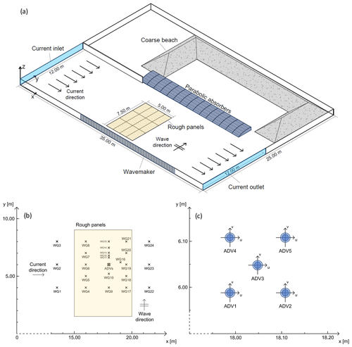
Figure 1Schematization of the experimental wave basin (a); positioning of the measurement instruments (b); detail on the positioning of acoustic Doppler velocimeters (c).
On one side, the basin is provided with a multi-paddle piston-type 18.00 m long wavemaker. The wavemaker front is 18.00 m wide and consists of 36 paddles, with each paddle being 1.20 m high and 0.50 m wide. The wavemaker is able to generate waves with wave height in the range 0.05÷0.45 m. To reduce wave reflection, a 18.75 m barrier made up of 15 parabolic steel absorbers is positioned 12 m away from the wavemaker. For the same purpose, a C-shaped coarse-grained material beach is located at the side opposite to the wavemaker.
A recirculation system allows the generation of a current, which is conveyed into (out of) the basin through a 12 m inlet (outlet). An electromagnetic flowmeter with a 10−4 m3 s−1 precision allowed monitoring the recirculating discharge. The still water level in the basin is measured by means of a meter stick. The bottom of the basin is horizontal and made of smooth concrete. In order to reproduce two different rough bottom conditions, a series of wood panels with fixed grains glued on top were positioned on the basin floor. Specifically, sand bed (SB) and gravel bed (GB) panels, with a 50 % fraction grain diameter d50=0.0012 and d50=0.025 m, respectively, were installed. The panels cover a rectangular area of 7.50×5.00 m, which hereinafter is called the controlled roughness area.
Water surface elevation was measured by means of 24 resistive wave gauges (WGs; Fig. 1b). The wave gauges were connected to a series of analog data loggers, which allowed the adjustment of gauge resolution and sensitivity. The WGs were distributed all over the area in front of the wavemaker in order to give detailed spatial information about the wave field. Four out of 24 WGs (specifically WG11 to WG14) were positioned in order to measure the wave reflection coefficient with the Faraci et al. (2015) method.
Flow velocities were measured by means of five acoustic Doppler velocimeters (ADVs); the model is the Vectrino+, manufactured by Nortek (Nortek, 2009). The ADVs were held together on a square chassis attached to a micrometer with a 0.0001 m precision, which allowed them to be slid vertically. The micrometer was then fixed to a bridge above the acquisition area. The distance between the ADVs in the x and y direction is larger than that recommended by the manufacturer of 0.12 m in order to ensure no acoustic interference between ADV transducers and receivers. The ADVs measured velocities within a cylindrical sampling volume of 0.001 m high, with a resolution of 0.001 m s−1. The accuracy is ±0.5 % of the measured value. The sampling frequency is set to 100 Hz. The ADV positions are shown in Fig. 1c. The performed plan of experiments is shown in Table 1.
Table 1Plan of experiments. Runs 1–18 are carried out over a sand bed (SB), whereas runs 19–36 are carried out over a gravel bed (GB). CO: current only, WO: wave only, WC: waves plus current, h: water depth, U: current velocity, H: wave height, T: wave period.
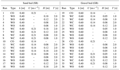
The experimental plan included current-only (CO), wave-only (WO), and wave-plus-current (WC) conditions. A total of 36 runs were carried out: Runs 1–18 over SB and Runs 19–36 over GB. Two different steady currents were generated by maintaining the current discharge constant (Q=1 m3 s−1) while changing the water depth h to 0.40 m or 0.60 m, corresponding to a mean current velocity of U=0.21 and 0.14 m s−1, respectively. The Froude number Fr for the two current conditions is Fr=0.106 (for U=0.21 m s−1) and Fr=0.058 (for U=0.14 m s−1). Different regular wave conditions were considered, with wave height m and wave period s.
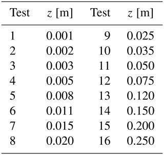
Each run consists of 16 tests, with each test having 3D velocity components measured at a different distance from bed z, in order to recover 16 positions along the vertical profile for each run with a specific wave–current configuration. A total of 576 tests were carried out. The measurement point distance from the bed is shown in Table 2.
In order to achieve a steady current, the current recirculation system was activated 1 h before starting the experiments. The sampling duration for CO tests is equal to 2 min. The sampling duration of WO and WC tests is 2 min for tests with wave period T=1.0 s and 4 min for tests with T=2.0 s, in order to collect 120 wave cycles for each test. The wavemaker is switched on 2 min before the start of the sampling process in order to achieve a stable wave field.
The model validation, in terms of variability of wave height, steadiness of the current, near orthogonality of the wave–current flow, development of the boundary layer, and other details, is thoroughly described in a previous study by Faraci et al. (2021).
3.1 Reynolds decomposition to obtain turbulent velocities
In order to obtain turbulent velocities, the measured velocity time series were decomposed into mean, phase-averaged, and turbulent components by means of Reynolds decomposition:
where u is the measured velocity, is the time-averaged velocity, is the phase-averaged velocity, and u′ is the turbulent (or fluctuating) velocity in the current direction. The same applies for v and w, respectively, in the wave and vertical upward direction. The time-averaged velocities , , and were obtained by time-averaging the instantaneous velocity time series measured by all the ADVs. Phase-averaged velocities in the current direction, , and wave direction, , were computed as follows:
where Nw is the number of waves used for the phase average. Waves were generated for 4 min for the wave period T=2.0 s and for 2 min for T=1.0 s in order to generate 120 waves per test, which is fairly larger than the minimum of 50 waves necessary for phase averaging (Sleath, 1987).
Turbulent velocities u′, v′, and w′ in the x, y, and z directions, respectively, were then obtained by subtracting the time-averaged and phase-averaged velocities from the instantaneous velocity time series.
This type of decomposition is, however, subject to possible contamination due to fluctuations of the wave height. In other words, if the oscillatory flow is not perfectly regular, fluctuations of wave height will contaminate the turbulent velocity component. To account for the incidence of oscillatory flow contamination, turbulent velocities were also computed using the empirical mode decomposition method, or EMD (Huang et al., 1998). EMD is a promising approach to decompose the signal and remove oscillatory contamination in the turbulent component from a time series due to large wave height variability. The procedure of EMD used in the present work follows the one described by Peruzzi et al. (2021), which employed EMD in wave–current interaction experiments characterized by substantial wave height variability. Figure 2 shows turbulence intensity profiles Iu (= ), which are an indication of the turbulence activity along the water column, for Run 22 (WC, H=0.08 m, T=2.0 s) and Run 21 (WC, H=0.08 m, T=1.0 s), obtained with the Reynolds decomposition (black circles) and EMD (gray crosses).
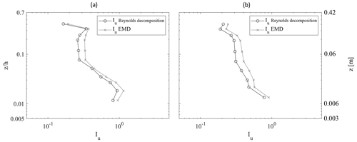
Figure 2Turbulence intensity profiles Iu () for Run 22 (WC, H=0.08 m, T=2.0 s) (a) and Run 21 (WC, H=0.08 m, T=1.0 s) (b), obtained with Reynolds decomposition (black circles) and with the EMD (gray crosses).
Run 22 (Fig. 2a) and Run 21 (Fig. 2b) have a wave-height-normalized standard deviation of 0.05 and 0.16, respectively, which are respectively the smallest and the largest wave height variability of the entire dataset. The decomposition of turbulence velocities using both Reynolds decomposition and EMD reveals that, despite variations in wave height, both methods produce similar turbulence intensity profiles. However, the EMD method consistently shows slightly higher turbulence intensity values. If the turbulent velocity time series were contaminated by Reynolds decomposition, an increase in Reynolds turbulence intensity relative to EMD would be expected. Instead, the opposite occurs: Reynolds decomposition results in lower turbulence intensity, suggesting that turbulence contamination from wave motion is not occurring. This finding is consistent across all experiments.
3.2 Turbulent velocity data pre-processing
Turbulent velocity data were processed in order to remove spikes in the time series. The presence of spikes is a common issue in acoustic velocimetry, and their removal (known as despiking) is considered an essential operation in velocity data processing (McLelland and Nicholas, 2000). However, a problem arises in turbulent flows as distinguishing spikes between actual turbulent fluctuations is crucial. Several despiking methods have been developed over the last decades (Goring and Nikora, 2002; Cea et al., 2007). The selected technique in this study is the one by Islam and Zhu (2013). This method employs a bivariate kernel density function to generate a density map of the data, effectively isolating the turbulent data cluster from surrounding spike clusters. This technique outperforms previous methods that rely on universal noise thresholds, especially in the presence of turbulent flows, ensuring the preservation of the slope of the turbulent velocity frequency spectrum. The maximum percentage of removed data is 15 %.
3.3 Space-averaged velocities
In rough flows, velocity flow fields are strictly related to the location of the point where they are measured. To investigate the spatially averaged characteristics of the flow, the velocity field close to a rough boundary can be made globally homogeneous by means of space averaging. The time-averaged velocities , , and , obtained by time-averaging the instantaneous velocities measured by all the ADVs, were further averaged in order to obtain time- and space-averaged , , and according to the following:
where NADV is the number of ADVs. The procedure of averaging by time and space is referred in the text as double averaging and allows filtering out the heterogeneous flow characteristics that depend to the specific position of the ADV.
3.4 Dimensional and nondimensional parameters
Significant dimensional quantities and nondimensional parameters were computed from double-averaged velocities to characterize the flow field. Current freestream velocity Uc was computed by depth-averaging the double-averaged current velocities above the expected current boundary layer upper limit (Fredsøe et al., 1999). Wave orbital velocity Uw was computed by considering the phase-averaged velocity maximums at the first measurement point above the wave boundary layer thickness. According to Fredsøe (1984), the expected wave boundary layer thickness in rough flows depends on the relative wave orbital amplitude , where Abm is the wave orbital amplitude (equal to ) and k is the bottom roughness. Once the expected wave boundary layer thickness is computed, the wave orbital velocity is measured considering the lowest measurement point above the wave boundary layer thickness in the crest velocity profile. Then, the orbital velocities measured by each ADV were space-averaged in order to obtain double-averaged orbital velocity Uw. Once Uc and Uw were obtained, current and wave Reynolds numbers were computed with the following set of equations:
where Abm is the wave orbital amplitude (, where is the wave frequency). A nondimensional wave–current parameter was computed as an indicator of the relative importance of the waves compared to the current. Moreover, the wave–current parameter is used to distinguish two wave–current regimes: the current-dominated regime () and the wave-dominated regime ().
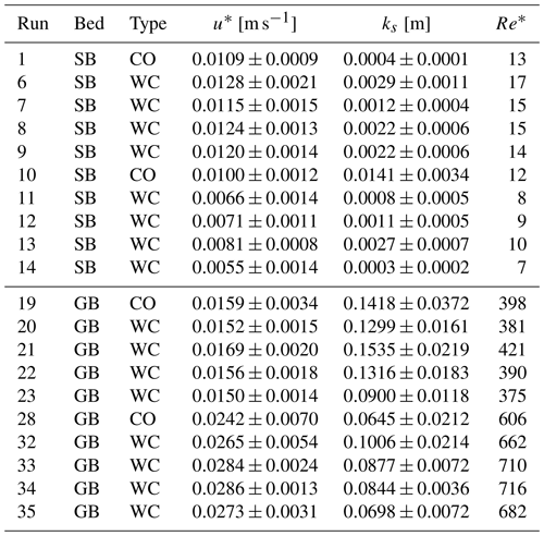
Current shear velocity u* and equivalent roughness ks were computed through a best-fitting technique (Sumer, 2007).
The best-fit procedure is different depending whether on the flow is hydraulically smooth, i.e., when the viscous sublayer thickness is larger than the bed grain size, or hydraulically rough, when the viscous sublayer is destroyed as the grains are larger than the supposed thickness of the viscous layer. In hydraulically smooth flow, the velocity profile in the logarithmic region follows the law of the wall,
where κ is the von Kármán constant (=0.4). In hydraulically rough flow, the near-bed velocity distribution follows a logarithmic law:
where , with ks being the equivalent roughness. In this case, a hypothesis on the position of the theoretical bottom needs to be made. The procedure follows the one suggested by Sumer (2007) by distinguishing between different hypotheses of theoretical bottom distance: the one that grants the larger logarithmic profile. Then, shear velocity was obtained from the slope of the linear fitting of u and log (z), whereas ks was obtained through its intercept.
The computations to obtain the shear velocity and related quantities are subject to uncertainty. Especially ks may be very different depending on the measurement chosen to be part of the logarithmic profile linear fitting. A 95 % confidence interval for the slope was computed by means of a Student's t distribution to assess the uncertainty range of the slope. A similar procedure was applied to ks. From the shear velocity the Reynolds shear number was then computed, according to the relation
Table 3 shows u* and ks alongside their confidence interval values and Re* for all CO and WC runs.
Table 3Shear velocity u*, equivalent roughness ks, and Reynolds shear number Re*. Confidence intervals for u* and ks are also reported.
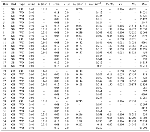
This specifically includes measured freestream current velocity Uc, measured orbital velocity Uw, wave–current regime parameter , current Reynolds number Rec, and wave Reynolds number Rew. Their values are shown in Table 4. Target current velocities were chosen to have a relatively “weaker” (Fr=0.058) and a “stronger” (Fr=0.106) current, both in subcritical flow (Fr<1). The current Reynolds number Rec is greater than 4000 for all the experiments; therefore, the regime is fully turbulent, whereas the wave boundary layer is laminar as according to Sumer et al. (2010).
Table 4Dimensional and nondimensional parameters for each experiment. Runs 1–18 are carried out over a sand bed (SB), whereas runs 19–36 were carried out over a gravel bed (GB). CO: current only, WO: wave only, WC: waves plus current; h is water depth, H is wave height, T is wave period, Uc is the freestream current velocity, Uw is the wave orbital velocity, Fr is the current Froude number, Rec is the current Reynolds number, and Rew is the wave Reynolds number.
4.1 Bed shear analysis
Current velocity profiles in the case of current only and waves plus current are compared in Fig. 3 to investigate the hydrodynamic effects of the waves superposed to the current.
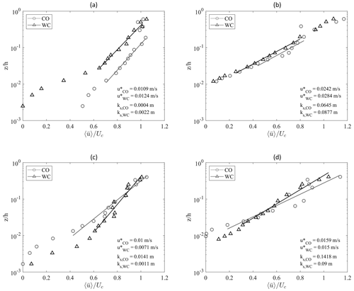
Figure 3Velocity profiles: (a) Run 1 (CO, SB, Fr=0.106, circles) and Run 8 (WC, SB, Fr=0.106, H=0.08 m, T=2.0 s, triangles); (b) Run 28 (CO, GB, Fr=0.106, circles) and Run 33 (WC, GB, Fr=0.106, H=0.08 m, T=2.0 s, triangles); (c) Run 10 (CO, SB, Fr=0.058, circles) and Run 12 (WC, Fr=0.058, H=0.12 m, T=2.0 s, triangles); (d) Run 19 (CO, GB, Fr=0.058, circles) and Run 23 (WC, GB, Fr=0.058, H=0.12 m, T=2.0 s, triangles).
Shear velocity u* and equivalent roughness ks are reported in the figure, alongside the fitting lines used for their computation (Sumer, 2007). Subscripts CO and WC indicate current-only and wave-plus-current conditions, respectively.
Figure 3a, which reports a comparison between runs 1 (CO) and 8 (WC, H=0.08 m, T=2.0 s), both of them over a sand bed and with Fr=0.106, shows that the superposition of the waves determines an increase in resistance experienced by the current, revealed by the increase in shear velocity by 14 % and an increase in equivalent roughness by more than an order of magnitude.
Analogously, Fig. 3b shows the comparison of Run 28 (CO) and Run 33 (WC, H=0.08 m, T=2.0 s) over a gravel bed with Fr=0.106. With respect to the sand bed case in Fig. 3a, a similar behavior is observed over the gravel bed, although in this case the CO shear velocity is more than doubled in comparison with that of the sand bottom runs due to the presence of the rough bottom. Also in this case shear velocity and equivalent roughness increase as waves are superposed to the current by 17 % and 35 %, respectively.
In comparison with the experiments shown in Fig. 3a and b, the experiments shown in Fig. 3c and d were carried out with a larger water level (from 0.40 to 0.60 m) in order to generate a weaker current (Fr=0.058). Specifically, Fig. 3c shows a comparison between Run 10 (CO) and Run 11 (WC, H=0.08 m, T=2.0 s), both of them over a sand bed.
In this case, the superposition of waves determines a reduction of bottom shear, with a decrease in u* of 40 % and a decrease in ks of an order of magnitude.
Similarly, Fig. 3d illustrates a comparison between Run 19 (CO) and Run 22 (WC, H=0.08 m, T=2.0 s) over a gravel bed with Fr=0.058. In this case a slight decrease is observed for both (6 %) and ks,WC (57 %).
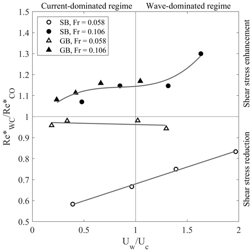
In order to provide an overall view of how the wave motion affects the current bottom flow, Fig. 4 shows the wave–current parameter versus the shear Reynolds number ratio for all the wave-plus-current tests.
The wave–current parameter indicates the relative strength of the wave motion compared to the current flow, separating the current-dominated regime () and the wave–dominated regime (). The shear Reynolds number ratio is an expression of the shear experienced by the current relative to the current-only case. indicates a shear stress reduction compared to the current-only case, whereas indicates a shear stress enhancement.
In the presence of a stronger current (Fr=0.106, full markers), the superposition of the oscillatory flow always determines an increase in bed resistance, as shown by the always being greater than 1, no matter the bed roughness. The superposition of the laminar wave boundary layer seems to determine a stress enhancement, proved by the increase in shear velocity and equivalent roughness. This is in accordance with most of experimental evidence in the literature (Grant and Madsen, 1979; Fernando et al., 2011a). As the relative importance of the waves increases, i.e., as increases, the shear seems to be enhanced in a nonmonotonous fashion, with a plateau around .
In the presence of a weaker current (Fr=0.058, empty markers), a different trend is observed, since the superposition of waves determines a decrease in flow resistance compared with the current-only case, as the ratio is always below 1. Specifically, two behaviors are reported depending on the bed roughness. Over SB, the shear increases with a linear trend as increases, whereas over GB, the shear experienced by the current remains fairly constant as increases, with values of relative shear stress closer to 1.
4.2 Turbulent flow analysis
An analysis of the turbulent velocity data was carried out and is presented in this section. Figure 5a shows turbulence intensities Iu along the current direction for Run 1 (CO), Run 7 (WC, H=0.12 m, T=2.0 s), and Run 8 (WC, H=0.08 m, T=2.0 s). All runs are over a sand bed with Fr=0.106.
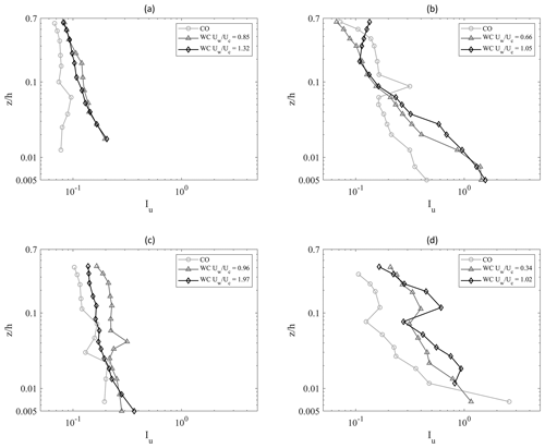
Figure 5Turbulence intensities Iu in the current direction. (a) Run 1 (CO), Run 7 (WC, H = 0.12 m, T=2.0 s, = 0.85), and Run 8 (WC, H=0.08 m, T=2.0 s, 2) over a sand bed with Fr=0.106. (b) Run 28 (CO), Run 33 (WC, H=0.08 m, T=2.0 s, = 0.66), and Run 34 (WC, H = 0.12 m, T=2.0 s, ) over a gravel bed with Fr=0.106. (c) Run 10 (CO), Run 11 (WC, H=0.08 m, T=2.0 s), and Run 13 (WC, H=0.18 m, T=2.0 s) over a sand bed with Fr = 0.058. (d) Run 19 (CO), Run 21 (WC, H=0.08 m, T=2.0 s), and Run 22 (WC, H=0.12 m, T=2.0 s) over a gravel bed with Fr=0.058.
It can be observed that the presence of the waves always enhances turbulence intensity, both close to and far from the bottom. Nevertheless, even though the relative importance of the waves to the current increases, turbulence intensity profiles tends to collapse on top of each other. This is supported by the fact that the two cases have a very similar value of .
Figure 5b shows turbulence intensities in the current direction Iu for Run 28 (CO), Run 33 (WC, H=0.08 m, T=2.0 s), and Run 34 (WC, H=0.12 m, T=2.0 s) over a gravel bed with the same current velocity Fr=0.106. The presence of the GB determines larger gradients of turbulence intensities in comparison with the corresponding SB case (Fig. 5a) with the same U. Notwithstanding the different wave–current regime, the two WC profiles show a very similar behavior. However, the increase in turbulence intensity in the larger- case (Run 34) seems to extend to a larger part of the water column (approximately up to 0.03÷0.04 ).
Figure 5c shows turbulence intensities Iu in the current direction of Run 10 (CO), Run 11 (WC, H = 0.08 m, T=2.0 s), and Run 13 (WC, H=0.18 m, T=2.0 s) over a sand bed with Fr=0.058. As increases, a turbulence intensity enhancement is observed in proximity to the bed, while there is a decrease in the upper part of the water column. The increase in the parameter also seems to affect the profile gradient in close proximity to the bottom boundary, determining an increase in the bottom turbulence intensity gradient.
Figure 5d shows turbulence intensities Iu of Run 19 (CO), Run 21 (WC, H=0.08 m, T=2.0 s), and Run 22 (WC, H=0.12 m, T=2.0 s) over a gravel bed with Fr=0.058. The figure shows a larger gradient of Iu in comparison with the corresponding sand bed case with the same U in Fig. 5c, approximately up to m. The CO case shows a larger turbulent intensity very close to the bottom boundary compared with all the corresponding WC cases. This could confirm the results of Fig. 3d, which shows a slightly larger shear experienced by the current in the absence of waves. However, such a behavior was not observed in the SB case in Fig. 5c. Moreover, slightly larger gradients of the turbulence intensity profiles are observed in the CO case.
Turbulence at a wall boundary in a steady flow is mainly generated by the succession of two cyclic events: ejections and sweeps (Corino and Brodkey, 1969). These events are mainly responsible for turbulent vertical momentum transport and determine most of the generation of Reynolds shear stress (Wallace, 2016). Quadrant analysis is a well-established technique to study the ejection–sweep cycle (Wallace et al., 1972; Lu and Willmarth, 1973; Kim et al., 1987). In quadrant analysis the turbulent events, defined as the fluctuating velocities at an instant t, where u′ and w′ are the streamwise and vertical upward direction turbulent velocities, are subdivided into four quadrants (Q1–Q4) depending on their signs. The second (, ) and the fourth ( and ) quadrants are the ones associated with the ejections and sweeps, respectively.
Figure 6a and b show the quadrant analysis for a current-only case (Run 1 SB, Fr=0.106) and a wave-plus-current case (Run 8, SB, Fr=0.106, H = 0.08 m, T=2.0 s), respectively, both at the same relative depth .
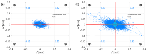
Figure 6Quadrant analysis of u′ and w′ for Run 1 (current only, SB, Fr=0.106) (a) and Run 8 (waves plus current, SB, Fr=0.106, H=0.08 m, T=2.0 s) (b).
The blue number inside each quadrant indicates the percentage of turbulent events that fall into the quadrant, excluding a central region defined by a hyperbolic threshold (Wallace, 2016), which excludes turbulent events not intense enough to be considered ejections or sweeps.
The dispersion of u′ and w′ around their mean value can be quantified by computing the determinant of the covariance matrix S:
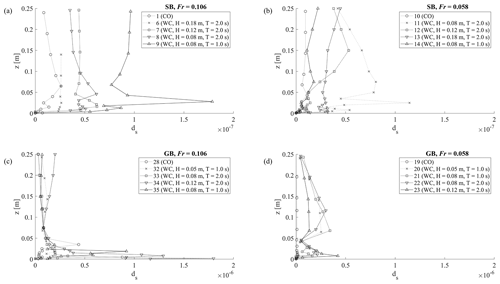
where and are the standard deviations of u′ and w′, respectively, whereas indicates the covariance of u′ and w′. While larger variances indicate more dispersion, a large covariance (whether positive or negative) indicates a stronger linear relationship between u′ and w′, which reduces the overall dispersion. Thus, the determinant decreases as covariance increases, reflecting the reduced spread in the 2D space due to the linear dependency between the variables. The determinant dS was computed for all tests and is shown in Fig. A1 in Appendix A.
Comparison between Fig. 6a and b illustrates that the presence of waves determines an increase in the intensity of turbulent activity, shown by the turbulent events being more dispersed, with dS increasing from to . However, the number of turbulent events above the hyperbolic threshold is almost halved in both ejection and sweep quadrants, with the number of events inside the hyperbolic hole reaching 62 %. Such a result indicates that the presence of the waves determines a decrease in the number of ejections and sweeps but at the same time an increase in their intensity.
In order to observe the occurrence of turbulent bursts during a wave phase, Fig. 7d illustrates the phase-averaged number of ejections and sweeps for Run 6 (WC, H=0.18 m, T=2.0 s) at . Figure 7c shows the correspondent phase-averaged wave velocity.
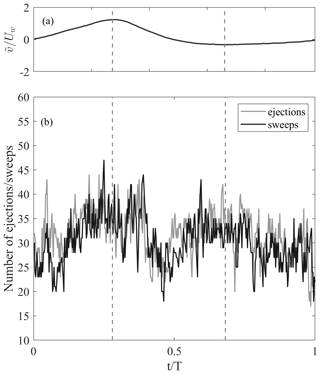
Figure 7Dimensionless phase-averaged wave velocity for Run 6 () (a); phase-averaged number of ejections and sweeps for Run 6, with the dashed line indicating wave crest and trough (b).
As the wave phase progresses, a clear oscillation in the number of turbulent bursts is observed. Turbulent bursts progressively increase when the wave phase progresses from nodes to antinodes, i.e., towards crest and through phases, whereas as wave phase progresses from antinodes to nodes, a reduction of the number of ejections and sweeps is observed. The reported pattern seems to follows the nonlinearity of the wave, with the increase in the number of bursts during the crest stage being shorter and more intense than the ones in the trough stage. This behavior appears to be consistent for both ejections and sweeps (black and gray line, respectively). This occurrence was observed for all the runs with larger wave height cases (H=0.12 m) but not easily recognizable for the cases with lower H, which showed no recognizable oscillation in the number of ejections and sweeps along the wave phase.
Results of our analysis highlighted that, depending on the bed roughness, freestream current velocity, and wave orbital velocity, current bottom shear stress can be enhanced or reduced due to wave motion. While current shear enhancement due to wave-generated turbulence is a well-documented occurrence in the literature, shear reduction is debated, although experimental evidence supports its occurrence under specific conditions. Lodahl et al. (1998) conducted experiments in a oscillating water tunnel and measured velocity fluctuations with a laser Doppler anemometer in wave- and current-dominated conditions. They observed that a turbulent current can be re-laminarized by the superimposition of the oscillatory flow, with the transition being dependent on the oscillatory flow Stokes' layer thickness. Lodahl and co-authors attributed this occurrence to the presence of the laminar wave boundary layer, which is experienced by the current as a decrease in bottom hydraulic roughness. In fact, the stress patterns reported by Lodahl and co-authors are reminiscent of the ones shown in Fig. 4. However, differently from Lodahl and co-authors, we also clearly observed a shear stress decrease in wave-dominated conditions. In this regard, an analogous finding was reported in the near-orthogonal wave–current experiments by Musumeci et al. (2006), which attributed the phenomenon to a re-laminarization process as well but also reported it in wave-dominated conditions. In accordance with Musumeci and co-authors, shear reduction is observed only in smooth conditions in our experiments as well, which resonates with analogous findings by Faraci et al. (2012), although in a very different model setup (waves and currents interacting over a sandpit).
Another main finding of our work regards turbulence features that emerged through the application of quadrant analysis, revealing a substantial difference when the wave motion is superposed to the current with respect to the current-only case. The analysis showed a reduction of the number of turbulent bursts, which was systematically accompanied by an increase in their intensity. A possible explanation involves the laminar to progressively more turbulent transition of the wave boundary layer. In fact, the presence of the (temporarily) laminar wave boundary layer might induce a shear reduction, which suppresses the current ejection and sweep production. As the wave boundary layer transitions to a more turbulent state, i.e., as the wave phase progresses from nodes to antinodes, the ejection–sweep cycle resumes and the intensity of the bursts increases due to wave-generated turbulence. This interpretation is corroborated by the cyclic increase–decrease in the turbulent bursts observed in Fig. 7b. This occurrence would explain both the overall decrease in the number of turbulent events in the current flow and the increase in the turbulence intensity fluctuations.
In the present work, an investigation of the hydrodynamics of near-orthogonal wave–current flow turbulence was carried out through a laboratory campaign. The hydrodynamics of the wave–current flow were investigated through a comparison of current-only experiments with experiments in the presence of superposed waves. Turbulent flow properties were investigated by studying fluctuating (turbulent) velocities. The data analysis highlighted the following main results.
-
Current bed shear is enhanced or reduced by wave motion depending on bed roughness, current freestream velocity, and wave orbital velocity, with a maximum current Re* increase of 31 % and a maximum decrease of 42 %. A decrease in bed shear is induced by the presence of the laminar wave boundary layer, which determines a decrease in shear velocity.
-
The current turbulent ejection–sweep mechanism follows an oscillatory pattern determined by the superposition of the wave motion. As the wave boundary layer develops, the number of turbulent bursts progressively increases (up to 47 phase-averaged events) or decreases (up to 16 phase-averaged events) from nodes to antinodes and from antinodes to nodes, respectively.
The results of this study have implications for the modeling of sediment entrainment, suspension, and transport in nearshore environments. These findings can be implemented in analytical and numerical models to predict sediment dynamics under the influence of both waves and currents. Future experimental studies should focus on (i) extending the range of experimental angles and Fr number to provide an extensive analysis of the influence of the wave motion on the current velocity profile and (ii) recovering direct measurements of bottom shear stresses rather than inferring them via indirect methods, for instance by using innovative methods based on ferrofluids of bioluminescence (Foti et al., 2010; Musumeci et al., 2018; Stancanelli et al., 2020).
Figure A1 shows the determinant of the covariance matrix of u′ as well as w′ and dS for all tests.
Data will be made available on request.
MM: conceptualization, data curation, formal analysis, investigation, methodology, software, validation, visualization, writing (original draft preparation; review and editing). CF: conceptualization, funding acquisition, investigation, project administration, supervision, writing (review and editing). BJ: investigation, methodology, resources, supervision, writing (review and editing). REM: conceptualization, funding acquisition, investigation, methodology, project administration, supervision, writing (review and editing).
The contact author has declared that none of the authors has any competing interests.
Publisher’s note: Copernicus Publications remains neutral with regard to jurisdictional claims made in the text, published maps, institutional affiliations, or any other geographical representation in this paper. While Copernicus Publications makes every effort to include appropriate place names, the final responsibility lies with the authors.
This article is part of the special issue “Oceanography at coastal scales: modelling, coupling, observations, and applications”. It is not associated with a conference.
This work was supported by the following projects: (i) the European Community's Horizon 2020 Research and Innovation Programme through the grant to HYDRALAB-PLUS (TA WINGS – Waves plus currents INteracting at a right anGle over rough bedS), contract no. 654110; (ii) REST-COAST – Large-scale RESToration of COASTal ecosystems through rivers to sea connectivity (call: H2020-LC-GD-2020; Proposal no. 101037097); (iii) National Recovery and Resilience Plan (NRRP), Mission 4 Component 2 Investment 1.3 – call for tender no. 341 of 15/03/2022 of Italian Ministry of University and Research funded by the European Union – NextGenerationEU – award number: PE00000005, concession decree no. 1522 of 11/10/2022 adopted by the Italian Ministry of University and Research, D43C22003030002, “Multi-Risk sciEnce for resilienT commUnities undeR a changiNg climate” (RETURN) – Cascade funding – Spoke VS1 “Acqua”, concession decree no. 2812 of 09/01/2024 adopted by the General Director of Politecnico di Milano, “Mitigation and Adaptation in Resilient Coastal and estUarine integrated unitS” (MARCUS); and (iv) “VARIO – VAlutazione del Rischio Idraulico in sistemi cOmplessi” of the University of Catania.
This work was supported by the following projects: (i) the European Community's Horizon 2020 Research and Innovation Programme through the grant to HYDRALAB-PLUS (TA WINGS – Waves plus currents INteracting at a right anGle over rough bedS), contract no. 654110; (ii) REST-COAST – Large-scale RESToration of COASTal ecosystems through rivers to sea connectivity (call: H2020-LC-GD-2020; Proposal no. 101037097); (iii) National Recovery and Resilience Plan (NRRP), Mission 4 Component 2 Investment 1.3 – call for tender no. 341 of 15/03/2022 of Italian Ministry of University and Research funded by the European Union – NextGenerationEU – award number: PE00000005, concession decree no. 1522 of 11/10/2022 adopted by the Italian Ministry of University and Research, D43C22003030002, “Multi-Risk sciEnce for resilienT commUnities undeR a changiNg climate” (RETURN) – Cascade funding – Spoke VS1 “Acqua”, concession decree no. 2812 of 09/01/2024 adopted by the General Director of Politecnico di Milano, “Mitigation and Adaptation in Resilient Coastal and estUarine integrated unitS” (MARCUS); and (iv) “VARIO – VAlutazione del Rischio Idraulico in sistemi cOmplessi” of the University of Catania.
This paper was edited by Davide Bonaldo and reviewed by Xuan Zhang and one anonymous referee.
Asano, T. and Iwagaki, Y.: Bottom turbulent boundary layer in wave-current co-existing systems, in: Coastal Engineering 1984, 2397–2413, https://doi.org/10.1061/9780872624382.162, 1985. a
Blondeaux, P.: Mechanics of coastal forms, Annu. Rev. Fluid Mech., 33, 339–370, 2001. a
Cea, L., Puertas, J., and Pena, L.: Velocity measurements on highly turbulent free surface flow using ADV, Exp. Fluids, 42, 333–348, 2007. a
Corino, E. and Brodkey, R.: A visual study of turbulent shear flow, J. Fluid Mech., 37, 30, https://doi.org/10.1017/S0022112073000844, 1969. a
Faraci, C., Foti, E., Marini, A., and Scandura, P.: Waves plus currents crossing at a right angle: Sandpit case, J. Waterw. Port Coast., 138, 339–361, 2012. a
Faraci, C., Scandura, P., and Foti, E.: Reflection of sea waves by combined caissons, J. Waterw. Port Coast., 141, 04014036, https://doi.org/10.1061/(ASCE)WW.1943-5460.0000275, 2015. a
Faraci, C., Scandura, P., Musumeci, R., and Foti, E.: Waves plus currents crossing at a right angle: near-bed velocity statistics, J. Hydraul. Res., 56, 464–481, 2018. a
Faraci, C., Musumeci, R. E., Marino, M., Ruggeri, A., Carlo, L., Jensen, B., Foti, E., Barbaro, G., and Elsaßer, B.: Wave-and current-dominated combined orthogonal flows over fixed rough beds, Cont. Shelf Res., 220, 104403, https://doi.org/10.1016/j.csr.2021.104403, 2021. a, b
Fernando, P. C., Guo, J., and Lin, P.: Wave–current interaction at an angle 1: experiment, J. Hydraul. Res., 49, 424–436, 2011a. a, b
Fernando, P. C., Lin, P., and Guo, J.: Wave–current interaction at an angle 2: theory, J. Hydraul. Res., 49, 437–449, 2011b. a
Foti, E., Faraci, C., Foti, R., and Bonanno, G.: On the use of bioluminescence for estimating shear stresses over a rippled seabed, Meccanica, 45, 881–895, 2010. a
Fredsøe, J.: Turbulent boundary layer in wave-current motion, J. Hydraul. Eng., 110, 1103–1120, 1984. a, b
Fredsøe, J., Andersen, K. H., and Sumer, B. M.: Wave plus current over a ripple-covered bed, Coast. Eng., 38, 177–221, 1999. a
Goring, D. G. and Nikora, V. I.: Despiking acoustic Doppler velocimeter data, J. Hydraul. Eng., 128, 117–126, 2002. a
Grant, W. D. and Madsen, O. S.: Combined wave and current interaction with a rough bottom, J. Geophys. Res.-Oceans, 84, 1797–1808, 1979. a, b
Grant, W. D. and Madsen, O. S.: The continental-shelf bottom boundary layer, Annu. Rev. Fluid Mech., 18, 265–305, 1986. a
Huang, N. E., Shen, Z., Long, S. R., Wu, M. C., Shih, H. H., Zheng, Q., Yen, N.-C., Tung, C. C., and Liu, H. H.: The empirical mode decomposition and the Hilbert spectrum for nonlinear and non-stationary time series analysis, P. Roy. Soc. Lond. A Mat., 454, 903–995, 1998. a
Islam, M. R. and Zhu, D. Z.: Kernel density–based algorithm for despiking ADV data, J. Hydraul. Eng., 139, 785–793, 2013. a
Kemp, P. and Simons, R.: The interaction between waves and a turbulent current: waves propagating with the current, J. Fluid Mech., 116, 227–250, 1982. a
Kemp, P. and Simons, R.: The interaction of waves and a turbulent current-Waves propagating against the current, J. Fluid Mech., 130, 73–89, 1983. a
Kim, J., Moin, P., and Moser, R.: Turbulence statistics in fully developed channel flow at low Reynolds number, J. Fluid Mech., 177, 133–166, 1987. a, b
Lim, K. Y. and Madsen, O. S.: An experimental study on near-orthogonal wave–current interaction over smooth and uniform fixed roughness beds, Coast. Eng., 116, 258–274, 2016. a, b
Lodahl, C., Sumer, B. M., and Fredsøe, J.: Turbulent combined oscillatory flow and current in a pipe, J. Fluid Mech., 373, 313–348, 1998. a, b
Lu, S. and Willmarth, W.: Measurements of the structure of the Reynolds stress in a turbulent boundary layer, J. Fluid Mech., 60, 481–511, 1973. a
Marino, M., Faraci, C., and Musumeci, R. E.: Shoaling waves interacting with an orthogonal current, J. Mar. Sci. Eng., 8, 281, https://doi.org/10.3390/jmse8040281, 2020. a
Mathisen, P. P. and Madsen, O. S.: Waves and currents over a fixed rippled bed: 1. Bottom roughness experienced by waves in the presence and absence of currents, J. Geophys. Res.-Oceans, 101, 16533–16542, 1996. a
McLelland, S. J. and Nicholas, A. P.: A new method for evaluating errors in high-frequency ADV measurements, Hydrol. Process., 14, 351–366, 2000. a
Musumeci, R. E., Cavallaro, L., Foti, E., Scandura, P., and Blondeaux, P.: Waves plus currents crossing at a right angle: Experimental investigation, J. Geophys. Res.-Oceans, 111, https://doi.org/10.1029/2005JC002933, 2006. a
Musumeci, R. E., Marletta, V., Sanchez-Arcilla, A., and Foti, E.: A ferrofluid-based sensor to measure bottom shear stresses under currents and waves, J. Hydraul. Res., 56, 630–647, 2018. a
Nortek, A.: Vectrino velocimeter user guide, Nortek AS, Vangkroken, Norway, 621, https://doi.org/10.1109/CWTM.2011.5759559, 2009. a
Olabarrieta, M., Medina, R., and Castanedo, S.: Effects of wave–current interaction on the current profile, Coast. Eng., 57, 643–655, 2010. a
Peruzzi, C., Vettori, D., Poggi, D., Blondeaux, P., Ridolfi, L., and Manes, C.: On the influence of collinear surface waves on turbulence in smooth-bed open-channel flows, J. Fluid Mech., 924, https://doi.org/10.1017/jfm.2021.605, 2021. a, b
Raushan, P. K., Singh, S. K., Debnath, K., Mukherjee, M., and Mazumder, B. S.: Distribution of turbulent energy in combined wave current flow, Ocean Eng., 167, 310–316, 2018. a
Roy, S., Samantaray, S. S., and Debnath, K.: Study of turbulent eddies for wave against current, Ocean Eng., 150, 176–193, 2018. a
Simons, R., Kyriacou, A., Soulsby, R., and Davies, A.: Predicting the nearbed turbulent flow in waves and currents, IAHR, 1988. a
Simons, R. R., Grass, T. J., and Mansour-Tehrani, M.: Bottom shear stresses in the boundary layers under waves and currents crossing at right angles, in: Coastal Engineering 1992, 604–617, https://doi.org/10.1061/9780872629332.045, 1993. a, b
Singh, S. K., Debnath, K., and Mazumder, B. S.: Spatially-averaged turbulent flow over cubical roughness in wave-current co-existing environment, Coast. Eng., 114, 77–85, 2016. a
Singh, S. K., Raushan, P. K., and Debnath, K.: Combined effect of wave and current in rough bed free surface flow, Ocean Eng., 160, 20–32, 2018. a
Sleath, J.: Turbulent oscillatory flow over rough beds, J. Fluid Mech., 182, 369–409, 1987. a
Soulsby, R., Hamm, L., Klopman, G., Myrhaug, D., Simons, R., and Thomas, G.: Wave-current interaction within and outside the bottom boundary layer, Coast. Eng., 21, 41–69, 1993. a
Stancanelli, L., Musumeci, R. E., Stagnitti, M., and Foti, E.: Optical measurements of bottom shear stresses by means of ferrofluids, Exp. Fluids, 61, 1–18, 2020. a
Styles, R., Glenn, S. M., and Brown, M. E.: An optimized combined wave and current bottom boundary layer model for arbitrary bed roughness, Tech. rep., US Army Engineer Research and Development Center, Coastal and Hydraulics, 2017. a
Sumer, M.: Lecture notes on turbulence, Technical University of Denmark, 2007, 2007. a, b, c
Sumer, M., Jensen, P. M., Sørensen, L. B., Fredsøe, J., Liu, P. L.-F., and Carstensen, S.: Coherent structures in wave boundary layers. Part 2. Solitary motion, J. Fluid Mech., 646, 207–231, 2010. a
Umeyama, M.: Reynolds stresses and velocity distributions in a wave-current coexisting environment, J. Waterw. Port Coast., 131, 203–212, 2005. a
Wallace, J. M.: Quadrant analysis in turbulence research: history and evolution, Annu. Rev. Fluid Mech., 48, 131–158, 2016. a, b, c
Wallace, J. M., Eckelmann, H., and Brodkey, R. S.: The wall region in turbulent shear flow, J. Fluid Mech., 54, 39–48, 1972. a
Yuan, J. and Madsen, O. S.: Experimental study of turbulent oscillatory boundary layers in an oscillating water tunnel, Coast. Eng., 89, 63–84, 2014. a, b
Zhang, X., Simons, R., Zheng, J., and Zhang, C.: A review of the state of research on wave-current interaction in nearshore areas, Ocean Eng., 243, 110202, https://doi.org/10.1016/j.oceaneng.2021.110202, 2022. a


